BOILERMATE 2000
For Gledhill BoilerMate 2000 Parts and Spares click on the following links: Gledhill BoilerMate 2000 Parts And Spares
DESIGN, INSTALLATION AND SERVICING INSTRUCTIONS
Gas Council Approved Reference Numbers
BoilerMate 125 89-317-04A
BoilerMate 145 89-317-05A
BoilerMate 185 89-317-06A
BoilerMate 210 89-317-07A
BoilerMate 225 89-317-08A
AN OPEN VENTED CENTRAL HEATING
AND MAINS PRESSURE HOT WATER SUPPLY
SYSTEM INCORPORATING
A THERMAL STORE
ALL MODELS COMPLY WITH THE
WATER HEATER MANUFACTURERS
SPECIFICATION FOR INTEGRATED THERMAL
STORES
CONTENTS
ISSUE 10: 06-08
| Section | Details |
| DESIGN | Introduction |
| Technical Data | |
| System Details | |
| INSTALLATION | Site Requirements |
| Installation | |
| Commissioning | |
| SERVICING | Annual Servicing |
| Changing Components | |
| Short Parts List | |
| Fault Finding | |
| Appendix A | |
| Appendix B | |
| Appendix C | |
| Appendix D | |
| Appendix E | |
| Terms & Conditions |

As part of the industry wide “Benchmark” Initiative all Gledhill BoilerMates now include a Benchmark Installation, Commissioning and Service Record Log Book. Please read carefully and complete all sections relevant to the appliance installation. The details of the Log Book will be required in the event of any warranty work being required. There is also a section to be completed after each regular service visit. The completed Log Book and these instructions should be left in the pocket provided on the back of the front panel.
The Gledhill BoilerMate range is a WBS listed product and complies with the WMA Specification for integrated thermal storage products. The principle was developed in conjunction with British Gas. This product is manufactured under an ISO 9001:2000 Quality System audited by BSI.
Patents Pending
The Gledhill Group’s first priority is to give a high quality service to our customers.
Quality is built into every Gledhill product and we hope you get satisfactory service from Gledhill.
If not please let us know.
DESIGN
1.1 INTRODUCTION
These instructions should be read in conjunction with the Installation and Servicing Instructions issued by the manufacturers of the heat source e.g. the boiler used.
Any water distribution and central heating installation must comply with the relevant recommendations of the current version of the Regulations and British Standards listed below:-
Gas Safety Regulations
Building Regulations
I.E.E. Requirements for Electrical Installations
Water Regulations
British Standards
BS6798, BS5449, BS5546, BS5440:1, BS5440:2,
CP331:3, BS6700, BS5258, BS7593 and BS7671.
A competent person as stated in the Gas Safety Regulations must install the BoilerMate heating system. The manufacturer’s notes must not be taken as overriding statutory obligations.
The BoilerMate 2000 is only suitable for use with an open vented central heating system.
The BoilerMate 2000 is not covered by section G3 of the current Building Regulations and is therefore not notifiable to Building Control.
The information in this manual is provided to assist generally in the selection of equipment. The responsibility for the selection and specification of the equipment must however remain that of the customer and any Designers or Consultants concerned with the design and installation.
Please Note: We do not therefore accept any responsibility for matters of design, selection or specification or for the effectiveness of an installation containing one of our products unless we have been specifically requested to do so.
All goods are sold subject to our Conditions of Sale, which are set out at the rear of this manual.
In the interest of continuously improving the BoilerMate range, Gledhill Water Storage Ltd reserve the right to modify the product without notice, and in these circumstances this document, which is accurate at the time of printing, should be disregarded. It will however be updated as soon as possible after the change has occurred.
DESIGN
If scale should ever become a problem the plate heat exchanger is easily isolated and quickly replaced with a service exchange unit which can be obtained at a nominal cost from Gledhill. For further details see Section 1 Hot and Cold Water System page 10.
The pcb also incorporates the facility to operate the heating pump for a few seconds every few days when the heating is not being used, to reduce the likelihood of the pumps sticking as well as providing a boiler pump overrun facility.
Any automatic boiler designed to operate on an 820C flow and a 710C return up to a maximum of 35kW can be linked to any suitable model of BoilerMate 2000 and the deciding factor is the space heating and the hot water requirements of a dwelling. See Section 1.2 Technical Data for further details.
The BoilerMate 2000 is available with the option of ‘Switch’ which will provide a 9kW electrical emergency backup in case of failure of the main heat source. See section 1.3 Syste
INTRODUCTION
Description
The BoilerMate 2000 shown schematically above is designed to provide improved space heating and mains pressure hot water when coupled to any remotely sited condensing or non condensing boiler - as long as they comply with the recommendations contained in the rest of this manual.
A report by the Cranfield Institute of Technology found that this system gives a potential for energy savings of up to 15%.
Because of the efficiency of the appliance improved SAP ratings can be achieved. Further details are available from the Gledhill Technical Department.
The principle of a BoilerMate 2000 is to separate the heat generator e.g. a boiler from heat emitters (radiators) by a thermal store, which evens out the fluctuating demands for heating and hot water. Thus, by storing energy produced when the demand is low and discharging it when the demand is high (i.e. during property warm up or when hot water is drawn off), a smaller boiler can potentially be used.
An important feature of this concept is that hot water can be supplied directly from the mains at conventional fl ow rates without the need for temperature and pressure relief safety valves or expansion vessels. This is achieved by passing the mains water through a plate heat exchanger. The outlet temperature of the domestic hot water is maintained by a printed circuit board, which controls the speed of the pump circulating the primary water from the store through the plate heat exchanger.
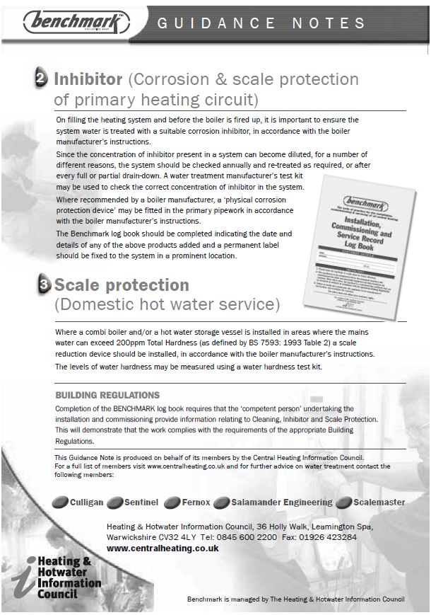
To comply with the Benchmark Guidance Note for Water Treatment in heating and hot water systems the installer should check the hardness levels of the water supply and if necessary fi t an in-line scale inhibitor/reducer to provide protection to the whole of the domestic water system.
DESIGN
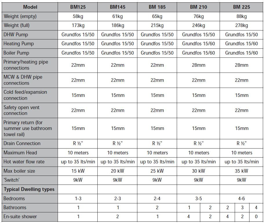
TECHNICAL DATA
Notes:-
1. The BoilerMate 225 appliance is suitable for use in large properties because it produces the same ‘peak hour output’ as a typical 350-400 litre unvented cylinder. [Ask for report - Unvented v’s Integrated Thermal Storage]. [Please note that this model requires a larger cupboard and a 686mm wide door]. For properties requiring the BM 225 the incoming main should be a minimum of 35mm MDPE with a pressure of not less than 2 bar dynamic and an adequate flow in line with the pipe sizing calculations. In many cases, properties of this size will benefit from having 2 smaller sized appliances located adjacent to the areas of peak hot water use. This will allow 2 heating zones to be provided and remove the need to provide a secondary circulation on the hot water system.
2. Plastic feed and expansion cistern will be supplied separately including ballvalve, float and overflow fitting.
3. The flow rates are based on a 35°C temperature rise and assume normal pressure and adequate flow to the appliance. The actual flow rate from the appliance is automatically regulated to a maximum of 28 litres/min.
4. Models will be available in Hard and Soft water versions (suffixed ‘H’ or ‘S’).
5. Unit is supplied on a 100mm high installation base.
6. The domestic hot water outlet temperature is automatically regulated to approximately 55°C at the bath flow rate of 18 litres/min recommended by BS 6700. The temperature is not user adjustable.
DESIGN
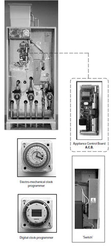
Standard Equipment
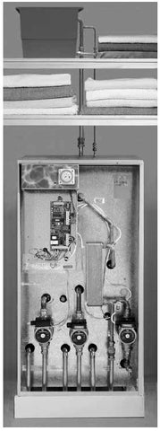
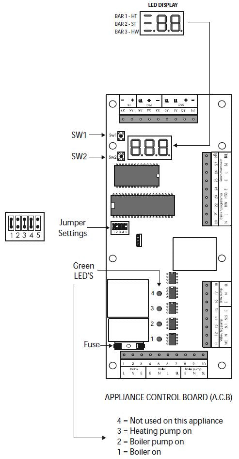
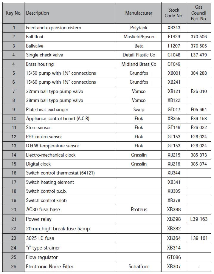
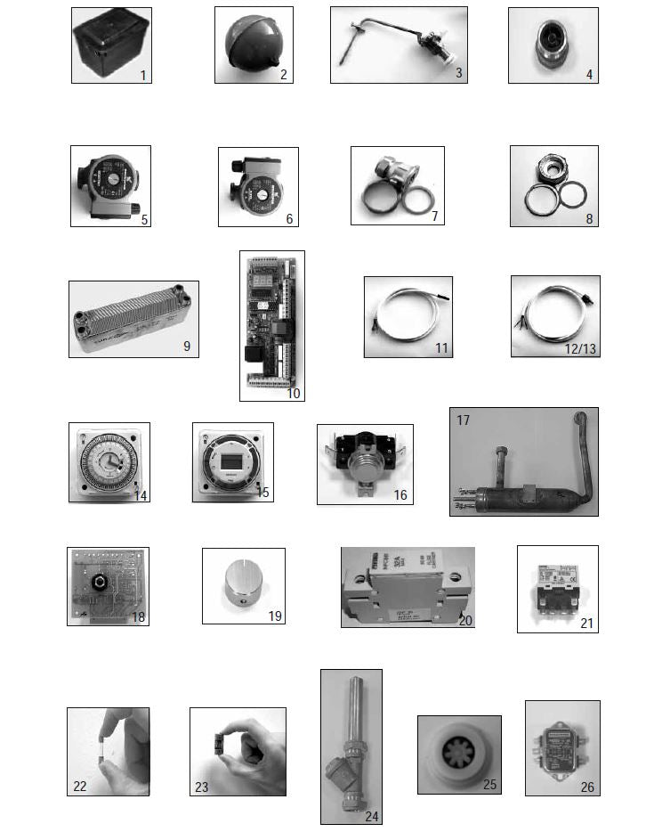
The standard configuration of the BoilerMate 2000 is shown opposite. The Appliance Control Board (A.C.B.), mounted inside the appliance, controls the operation of the complete system. The A.C.B. is pre-wired to a terminal strip where all electrical connections terminate. It is supplied with the following factory fitted equipment:-
1. Boiler pump
2. Domestic hot water primary (plate heat exchanger) pump
3. Space heating pump
4. Hard water appliance control board (A.C.B.) 5. Electro-mechanical clock to control the space heating (in conjunction with room thermostat - if fitted)
6. Plate heat exchanger
7. DHWS temperature sensor
8. PHE return sensor
9. Store temperature sensor
10. Y type strainer/flow regulator
11. A feed and expansion cistern complete with ballvalve, overflow fitting and cold feed/open vent pipework assembly is supplied separately.
Optional Equipment
* A soft water model is available for areas where the hardness level is below 200 p.p.m. (mg/ltr)
* Flexible connectors for quick connection to first fi x pipe installation. For further details see 2.2 Installation, Pipework connections.
* ‘Switch’ emergency electrical back-up for heating and hot water in the event of a boiler fault.
* A seven day digital clock/programmer to control the space heating (in conjunction with a room thermostat if fitted).
* A kit to site the clock/programmer remotely.
* A no clock option - because of the design of the appliance it should not be necessary to fit anything other than a single channel clock to control the heating system.
* Hot and cold water manifolds for use with plastic pipework.
DESIGN

APPLIANCE DIMENSIONS
| Model | Height A | Width B | Depth C |
| BM 125 | 1140mm | 595mm | 595mm |
| BM 145 | 1140mm | 595mm | 595mm |
| BM 185 | 1350mm | 595mm | 595mm |
| BM 210 | 1500mm | 595mm | 595mm |
| BM 225 | 1550mm | 650mm | 595mm |
Note: The Appliance dimensions above do not allow for the100mm high installation base
The following table of minimum cupboard dimensions only allow the minimum space required for the appliance (including the F & E cistern) and any extra space required for shelving etc in the case of airing cupboards etc must be added.
| Model | Height F | Width D | Depth E |
| BM 125 | 1890mm | 700mm | 600mm |
| BM 145 | 1890mm | 700mm | 600mm |
| BM 185 | 2100mm | 700mm | 600mm |
| BM 210 | 2250mm | 700mm | 600mm |
| BM 225 | 2300mm | 750mm | 600mm |
The BM 225 is wider than the other sizes and requires a minimum 686mm wide door and a 750mm wide cupboard.
Note: The above dimensions are based on the Appliance and the F & E cistern being in the same cupboard.
DESIGN
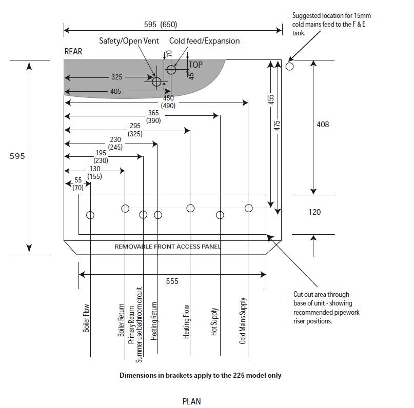
The BoilerMate 2000 units are supplied on an installation base to allow the pipe runs to connect to the appliance from any direction. It is easier if all pipes protrude vertically in the cut out area shown. Compression or push fit connections can be used and we do offer a set of flexible connectors as an option. All pipe positions are approximate and subject to a tolerance of +/- 20mm in any direction. A 15mm cold water supply and a 22mm warning / overflow pipe will also be required for the separate feed and expansion tank.
DESIGN
AWAITING HOT WATER PERFORMANCE GRAPHS FOR EACH MODEL SIZE
TO BE ADDED
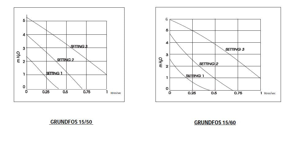
PERFORMANCE GRAPHS OF GRUNDFOS PUMPS
DESIGN
SYSTEM DETAILS
Hot and Cold Water System
General
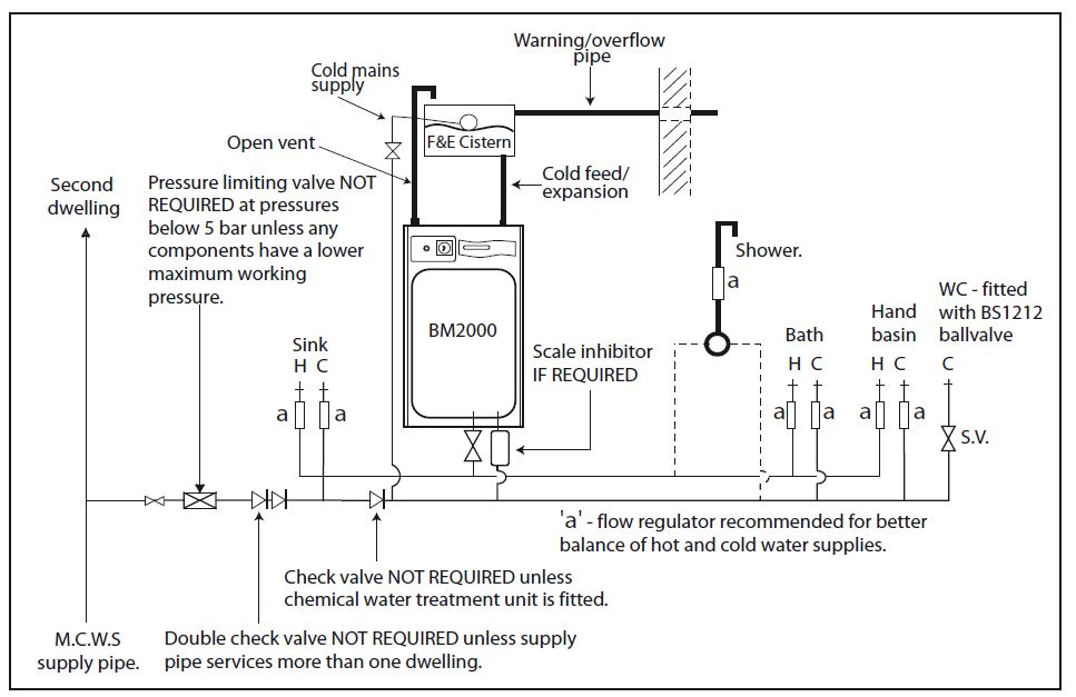
A schematic layout of the hot and cold water services in a typical small dwelling is shown below. BoilerMate 2000 will operate at mains pressures as low as 1 bar and as high as 5 bar although the recommended range is 2-3 bar. If the manifolds (available as an optional extra) are being used the inlet pressure to the manifold must be a minimum of 2 bar. It is also important to check that all other equipment and components in the hot and cold water system are capable of accepting the mains pressure available to the property. If the mains pressure can rise above 5 bar or the maximum working pressure of any item of equipment or component to be fitted in the system a pressure limiting (reducing) valve set to 3 bar will be required.
If you encounter a situation where the water pressure is adequate but flow rates are poor please contact our technical helpline for details of an effective solution.
Note: Each BoilerMate 2000 is fitted with a strainer and flow regulator on the cold mains supply connection. If the supply pressure is less than 2 bar or if the manifolds (available as an optional extra) are being used or if all taps are provided with flow regulators the flow regulator on the cold inlet should be removed.
No check valve or similar device should be fitted on the cold water supply branch to the BoilerMate 2000.
To comply with the Benchmark Guidance Note for Water Treatment in Heating and Hot Water Systems the installer should check the hardness level of the water supply and if necessary fi t an in-line scale inhibitor/reducer to provide protection to the whole of the domestic water system. See Appendix C for a copy of the relevant part of the Benchmark Guidance Note.
When specifying this appliance we would recommend that for hardness levels above 200ppm (mg/l) a hard water appliance is used. For hardness levels above 250ppm (mg/l) we would recommend that some form of in-line scale inhibitor/reducer is recommended by one of the Water Treatment companies listed in the Benchmark Guidance Note (see Appendix C).”
The hot water flow rate from the BoilerMate 2000 is directly related to the adequacy of the cold water supply to the dwelling. This must be capable of providing for those services, which could be required to be supplied simultaneously, and this maximum demand should be calculated using procedures defined in BS 6700.
If a water meter is fitted in the service pipe, it should have a nominal rating to match the maximum hot and cold water peak demands calculated in accordance with BS 6700. This could be up to 80ltr/min in some properties.
DESIGN
Hot and Cold Water System
Pipe Sizing / Materials
To achieve even distribution of the available supply of hot and cold water, it is important in any mains pressure system, that the piping in a dwelling should be sized in accordance with BS 6700. This is particularly important in a large property with more than one bathroom.
However, the following rule of thumb guide lines should be adequate for most smaller property types as long as water pressures are within the recommended range of 2-3 bar.
1. A 15mm copper or equivalent external service may be sufficient for a small 1bathroom dwelling (depending upon the flow rate available), but the minimum recommended size for new dwellings is 22mm (25mm MDPE).
2. The internal cold feed from the main incoming stop tap to the BoilerMate should be run in 22mm pipe. The cold main and hot draw-off should also be run in 22mm as far as the branch to the bath tap.
3. The final branches to the hand basins and sinks should be in 10mm and to the baths and showers in 15mm. (1 metre minimum)
4. We would recommend that best results for a balanced system are achieved by fitting appropriate flow regulators to each hot and cold outlet. This is particularly relevant where the water pressures are above the recommended water pressure range of 2-3 bar. Details of suitable flow regulators are provided in Appendix A.
Note: If manifolds (available as an optional extra) are being used suitable flow regulators are automatically provided in the manifold and do not need to be provided at each outlet - See Appendix B for further details.
All the recommendations with regard to pipework systems in this manual are generally based on the use of BS/EN Standard copper pipework and fittings.
However, we are happy that plastic pipework systems can be used in place of copper internally as long as the chosen system is recommended for use on domestic hot and cold water systems by the manufacturer and is installed fully in accordance with their recommendations.
This is particularly important in relation to use of push fi t connections when using the optional flexible hose kits - see 2.2 Installation, Pipework connections.
It is also essential that if an alternative pipework material/system is chosen the manufacturer confirms that the design criteria of the new system is at least equivalent to the use of BS/EN Standard copper pipework and fittings.
Taps/Shower Fittings
Aerated taps are recommended to prevent splashing. Any type of shower mixing valve can be used as long as both the hot and cold supplies are mains fed. However, all mains pressure systems are subject to dynamic changes particularly when other hot and cold taps/showers are opened and closed, which will cause changes in the water temperature at mixed water outlets such as showers. For this reason and because these are now no more expensive than a manual shower we strongly recommend the use of thermostatic showers with this appliance. The shower head provided must also be suitable for mains pressure supplies. However, if it is proposed to use a ‘whole body’ or similar shower with a number of high flow/pressure outlets please discuss with the Gledhill technical department.
The hot water supply to a shower-mixing valve should be fed wherever practical directly from the BoilerMate 2000 or be the first draw-off point on the hot circuit. The cold supply to a shower-mixing valve should wherever practical be fed directly from the rising mains via an independent branch. The shower must incorporate or be fitted with the necessary check valves to provide back-syphonage protection in accordance with the Water Regulations. The supply of hot and cold mains water directly to a bidet is permitted provided that it is of the over-rim flushing type and that a type ‘A’ air gap is incorporated.
Hot and Cold Water System.
If the length of the hot water draw off pipework is excessive and the delivery time will be more than 60 seconds before hot water is available at the tap, you may wish to consider using trace heating to the hot water pipework such as the Raychem HWAT system. Please consult Gledhill Technical Department for further details.
It is important that the cold water pipework is adequately separated/protected from any heating/hot water pipework to ensure that the water remains cold and of drinking water quality.
Heating System
General
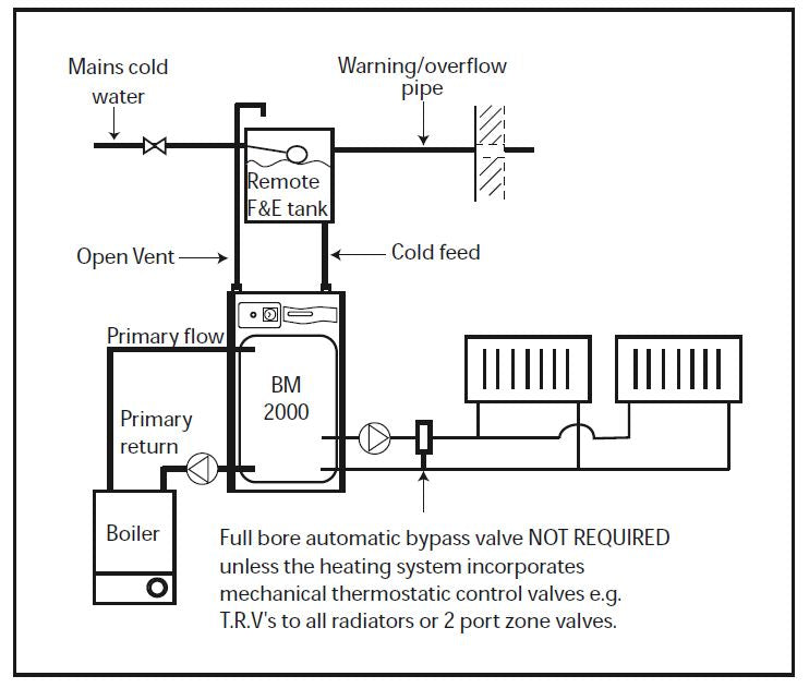
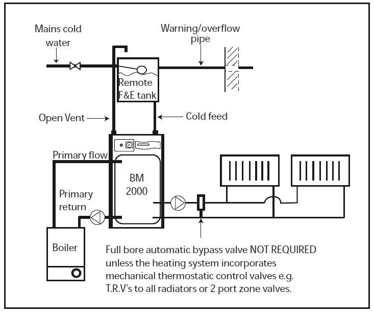
A schematic layout of the heating system in a typical small dwelling is shown opposite.
The flow and return from the boiler must always run directly to the BoilerMate 2000 and the flow should rise continuously to facilitate venting. The heating circuit is taken from the BoilerMate 2000 and is piped in the conventional manner.
The BoilerMate 2000 is only suitable for an open vented system.
The F & E cistern can be fitted remotely up to 10m above the base of the BoilerMate 2000 i.e. the maximum static pressure in the store must not exceed 1 bar.
If any radiators are located above the level of the BoilerMate 2000 the system should be designed so that gravity circulation does not occur when the heating pump is not running. To be certain of preventing this it is recommended that a check valve, or valves, are fitted on the vertical flow pipes.
The water level in the F & E cistern should be at least 250mm above the highest point on the system including the radiators and must be high enough to provide the minimum head required by the boiler being used.
The boiler manufacturer’s instructions with regard to minimum head must always be followed. This is particularly important in situations where the headroom is restricted (e.g. in a flat).
Range rated boilers can be used but should always be set at the highest output. The system efficiency will not be impaired while the recovery rate will be improved.
It is not necessary to provide a boiler bypass on the primary circuit with thermal storage appliances (i.e. between the boiler and the thermal store.)
DESIGN
Pipe Sizing/Materials
The primary pipework connecting the boiler and the thermal store should be sized to achieve a maximum of 8°C rise across the boiler or the maximum temperature rise specified by the boiler manufacturer, whichever is smaller, but in any instance it should not be less than 22mm copper tube.
Note: There should be no valves in the pipework connecting the boiler to the BoilerMate 2000.
The heating circuit operates on the normal primary boiler temperatures i.e. 82°C flow and 71°C return. Therefore any traditional hot water radiators or convectors can be used with this system and no special over-sizing of the heat emitters is necessary.
All the recommendations with regard to pipework systems in this manual are generally based on the use of BS/EN Standard copper pipework and fittings.
However, we are happy that plastic pipework systems can be used in place of copper internally as long as the chosen system is recommended for use on domestic heating systems by the manufacturer and is installed fully in accordance with their recommendations. We always recommend the use of barrier pipe for these systems.
Heating System
It is also essential that if an alternative pipework material/system is chosen the manufacturer confirms that the design criteria of the new system is at least equivalent to the use of BS/EN Standard copper pipework and fittings.
Boiler Size
It is only necessary to calculate the heating requirements in accordance with BS 5449. The allowances shown below should be added for domestic hot water. The control system automatically gives priority to hot water when necessary.
Allowance for Domestic Hot Water
| Model | (kW) |
| BM125 | 2 |
| BM145 | 3 |
| BM185 | 3 |
| BM210 | 3.5 |
| BM225 | 4 |
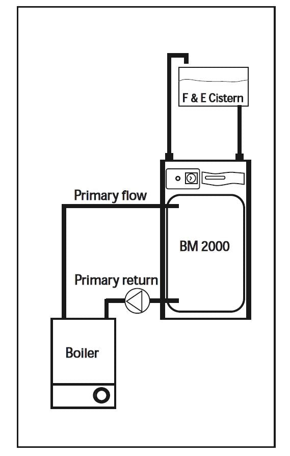
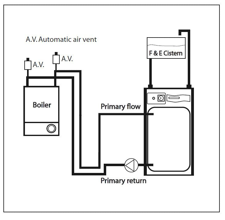
Boiler Sited Below BoilerMate 2000
Any boiler can be used when the flow pipe from the boiler to the BoilerMate 2000 rises continuously. No valve shall be fitted in the primary flow or open vent.
DESIGN
Boiler sited above the BoilerMate
Heating System
Any boiler used must be fitted with an overheat thermostat i.e. it must be suitable for use in a sealed system.
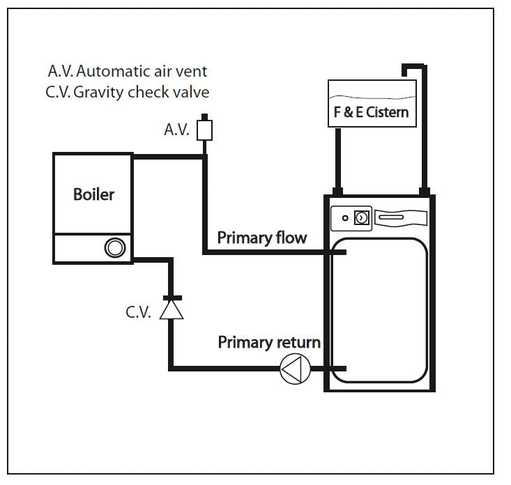
The F & E cistern must be fitted at a height which will provide the minimum head required for the boiler and must be at least 250mm above the highest point of the system.
The height of the water level in the F & E cistern from the base of the store should be no greater than 10m.
A gravity check valve should be fitted in the boiler return pipework to prevent gravity circulation between the BoilerMate 2000 and the boiler during dormant periods.
An automatic air vent will be required on the flow adjacent to the boiler and depending upon the pipe layout a manual air vent may also be required on the return adjacent to the boiler.
 Boiler sited with dipped flow and return pipes to the BoilerMate
Any boiler must be fitted with an overheat thermostat i.e. it must be approved for use in a sealed system.
An automatic air vent will be required on the flow and return connections adjacent to the boiler.
The height of the water level in the F & E cistern must provide the minimum head required by the boiler and must be at least 250mm higher than the highest point of the system.
DESIGN
Heating System
Connection of Bathroom Radiator/ Towel-Rail for Summer use
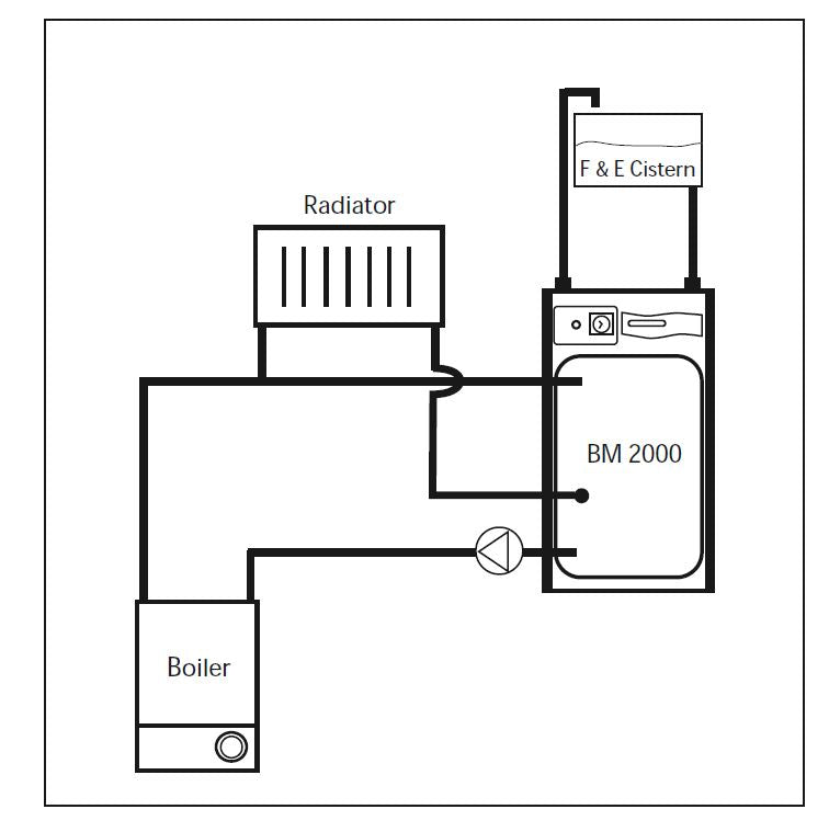
If a pumped circuit is required for the bathroom radiator/towel rail, the flow pipework can be teed anywhere into the primary flow between the boiler and the BoilerMate. The return pipework can be connected into the 15mm copper blanked connection provided adjacent to the boiler pump. We recommend any radiators/towel rails on this circuit are provided with T.R.V.’s and that the total heat output of the radiators/towel rails is not more than 5% of the boiler output.
The radiators will only get hot when the boiler is firing.
It is important that the flow rates through these radiators is adjusted to the minimum required at the lockshield valves on the radiators. If this is not done the performance of the BoilerMate will be adversely affected.
The height of the water level in the F & E cistern must provide the minimum head required by the boiler and must be at least 250mm higher than the highest point of the system.
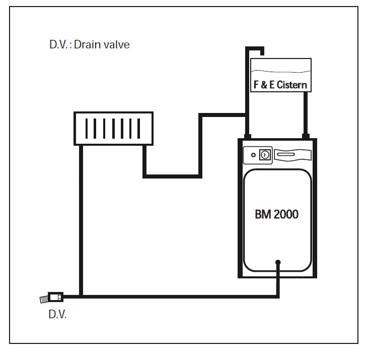
If heating of a single bathroom radiator or towel rail is required in summer, then it can be piped as a gravity circuit. The flow pipe to the radiator can be teed into the safety open vent pipe and the return pipe from the radiator can be connected to the store drain connection and the drain moved to the return pipe. The radiator can be fitted with a T.R.V. if required as long as this is suitable for gravity circulation i.e. low resistance type.
The height of the water level in the F & E cistern must provide the minimum head required by the boiler and must be at least 250mm higher than the highest point of the system.
DESIGN
Heating System
Method of connecting two BoilerMates to one heat source.
If the primary flow and return pipework continuously rises from the boiler to the BoilerMate the recommended method for connecting two BoilerMates to one heat source is to fit the BoilerMates as normal but to provide a single check valve on the branch immediately after each primary pump.
The heating and hot water from each appliance must serve separate zones/bathrooms within the property.
The electrical supplies from each appliance to the boiler will need twinning so that the boiler will operate on a call from either/both appliances.
Both primary pumps and the primary pipework sizes should be checked to ensure that they are adequate for the system that has been installed.
If the primary pipework dips or the boiler is located above the BoilerMate a single F & E cistern with a cold feed and open vent piped to the cistern should be used. This arrangement is not suitable for BoilerMate appliances fitted with Switch.
If it is proposed to use this arrangement please advise Gledhill at the time of order, Gledhill will then supply a suitable vent assembly for fitting on the safety/open vent connection and a blank for the cold feed connection of each BoilerMate 2000, in lieu of the F & E cistern normally provided.
If the boiler is a long way from the BoilerMate the resistance should be checked to ensure the pumps cannot produce a negative pressure in the BoilerMate appliance.
The single F & E cistern will need to be provided, (by the installer) and be suitable for the size of the total system installed. For further details please ring the Gledhill Technical helpline.
DESIGN
‘Switch’
The BoilerMate 2000 can be ordered with the option of ‘Switch’ which provides a 9kW electrical emergency back up in the case of failure of the main heat source i.e. gas boiler.
This must NOT be used to provide hot water only in summer if the main system is working correctly.
If Switch is ordered the electrical supply will need to take account of the increased load. Full details of the requirements are provided in Section 2.1 Site Requirements and 2.2 Installation.
Otherwise the design requirements are the same as the standard appliance.
Switch can operate on ‘hot water’ or ‘hot water and heating’ modes. In the former only hot water pump and electric heating element are energized. In the latter the heating system pump is also energized. This means that the heating will be on permanently unless manually switched back to the ‘hot water’ only position.
It also means that wherever Switch is being used the normal domestic hot water temperature controls are over-ridden. Initially dependent on the flow rate/store temperature hot water can be delivered at the tap at temperatures as high as 75°C. A warning notice to this effect is provided in the front of the appliance.
However, once the initial store temperature has been reduced the Switch element thermostat will reduce the temperature at the tap to no more than 65°C. Full details of how to operate the system are provided on a label fixed to the front of the appliance.
INSTALLATION
SITE REQUIREMENTS
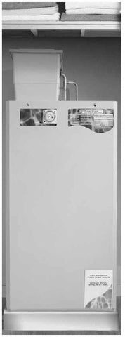
The appliance is designed to be installed in an airing/cylinder cupboard and the relevant minimum dimensions are provided in section 1.2 Technical Data.
Because of the ease of installation we recommend that the cupboard construction is completed and painted before installation of the appliance. The cupboard door can be fitted after installation. If the unit needs to be stored prior to installation it should be stored upright in a dry environment and on a level base/floor.
Installation and maintenance access is needed to the front of the appliance and above the F & E cistern. See Technical Data section for further details.
The minimum dimensions contained in section 1.2 Technical Data allow for the passage/connection of pipes to the appliance from any direction as long as the appliance is installed on the installation base provided. If the installation base is not used extra space may be needed to allow connection to the pipework and the whole of the base area should be continuously supported on a material which will not easily deteriorate if exposed to moisture.
The floor of the cupboard needs to be level and even and capable of supporting the weight of the appliance when full. Details of the weight when full is provided in section 1.2 Technical Data.
The appliance is designed to operate as quietly as practicable. However, some noise (from pumps etc) is inevitable in any heating system. This will be most noticeable in cupboards formed on bulkheads, or at the mid span of a suspended floor. In these cases the situation can be improved by placing the appliance on a suitable sound deadening material (i.e. carpet underlay or similar).
Cupboard temperatures will normally be higher than in a conventional system and the design of the cupboard and door will need to take this into account. No ventilation is normally required to the cupboard.
A suitable location will be needed for the separate feed and expansion cistern. This will often be at high level in the cupboard housing the BoilerMate 2000. The dimensions and clearances are provided in section 1.2 Technical Data. The location will need to provide a suitable route for the cold feed and expansion pipe as well as the open safety vent pipe. The location will also need to provide a suitable route and discharge position for the warning/overflow pipe and the ballvalve supply from the mains cold water system.
 INSTALLATION
Preparation/placing the appliance in position.
Details of the recommended positions for termination of the first fix pipework are provided in section 1.2 Technical Data. The pipework can be located or its position checked using the template provided with each appliance. If these have been followed installation is very simple and much quicker than any other system.

The appliance is supplied shrink wrapped on a timber installation base. Carrying handles are also provided in the back of the casing.
The feed and expansion cistern complete with ballvalve, cold feed/expansion and overflow/ warning fittings are provided in a separate box. If flexible connections have been ordered these will also be inside the feed and expansion cistern.
The appliance should be handled carefully to avoid damage and the recommended method is shown opposite. Before installation the site requirements should be checked and confirmed as acceptable. The plastic cover and protective wrapping should be removed from the appliance the installation base (provided) placed in position.
The appliance can then be lifted into position in the cupboard on top of the base and the front panel removed by unscrewing the 2 screws and lifting the door up and out, ready for connection of the pipework and electrical supplies. The feed and expansion cistern support shall be installed ensuring that the base is fully supported and the working head of the appliance is not exceeded and the recommended access is provided for maintenance - see section 1.2 Technical Data.
Note: Although the above guidance is provided any manual handling/lifting operations will need to comply with the requirements of the Manual Handling Operations Regulations issued by the H.S.E.
The appliance can be moved using a sack truck on the rear face although care should be taken and the route should be even. In apartment buildings containing a number of storeys we would recommend that the appliances are moved vertically in a mechanical lift. If it is proposed to use a crane expert advice should be obtained regarding the need for slings, lifting beams etc.
INSTALLATION
Pipework connections
The position of the pipework connections is shown opposite. The connection sizes and dimensions are listed in Section 1.2 Technical Data.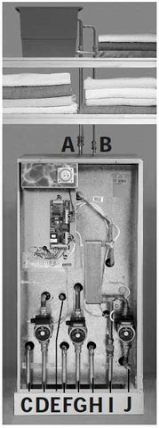
All the connections are also labelled on the appliance. It is essential that the pipework is connected to the correct connection. The connections can be hard piped but we recommend the use of flexible connections (available as an optional extra). If using push fi t connectors with the flexible hose kits it is important to check that they are compatible. Written approval has already been obtained for:-
Hepworth - Hep2O BiTite
John Guest - Speedfit
Yorkshire - Tectite
However, as similar assurances cannot be obtained for Polypipe fittings we cannot recommend their use.
Connections A, B, C, F and H are plain ended copper pipe. Connections D, G and I are compression fittings. Connection E is blanked 15mm copper pipe Connection J is RC½ (½ in BSPT internal).
A - Safety open vent
B - Cold feed/expansion
C - Primary flow (from boiler)
D - Primary return (to boiler)
E - Towel rail circuit return
F - Central heating return
G - Central heating flow
H - Domestic hot water
I - Incoming mains cold water
J - Drain (valve is not provided with the appliance)
Note: The safety open vent and cold feed/ expansion should be connected to the F & E cistern using the pipework assembly provided.
All factory made joints should be checked after installation in case they have been loosened during transit. The fittings for the feed and expansion cistern should be installed following the instructions provided by the manufacturer in a position to suit the particular location and the cistern fitted on its supports/base.
The cold feed/expansion and safety open vent should be installed between the appliance and the feed and expansion cistern.
INSTALLATION
It is normally envisaged that the feed and expansion cistern will be located in the same cupboard as the BoilerMate appliance itself to maintain a dry roof space.
The cold feed/open vent pipework assembly (as supplied) should be used if it is intended to install the F & E cistern directly on top of the appliance
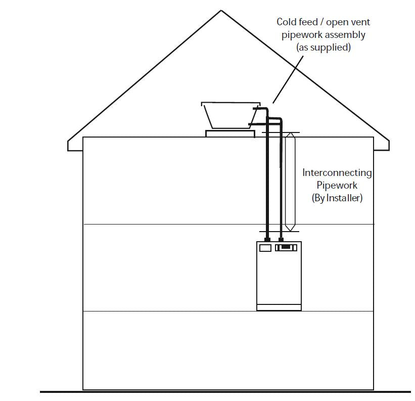
However, if it is necessary to locate the cistern in the roof space (or on a higher floor) the cold feed/open vent pipework assembly (as supplied) should be used to connect to the F &E cistern and pipework site run by the installer to connect this to the appliance.
Obviously, any pipework in the roof space and the feed and expansion cistern will need to be adequately insulated to protect against frost damage.
Combined feed and open vent pipe arrangements must not be used.
No valves should be fitted in the safety open vent which must be a minimum of 22mm copper pipe or equivalent. The overflow/warning pipe shall have a continuous fall, be fitted to discharge clear of the building and be sited so that any Overflow can be easily observed. It shall also be installed in a size and material suitable for use with heating feed and expansion cisterns in accordance with BS 5449 and should not have any other connections to it.
INSTALLATION
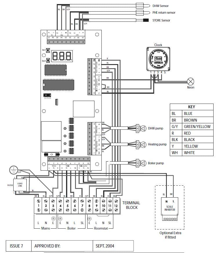
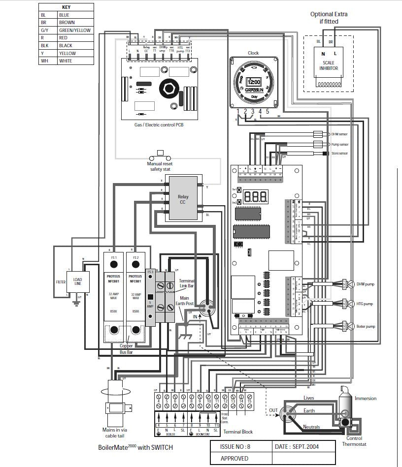
WIRING DIAGRAM - STANDARD BOILERMATE 2000 APPLIANCE
INSTALLATION
Electrical Connection - Standard Appliance
The BoilerMate 2000 is pre-wired to a 12 way terminal strip from the A.C.B. and plumbers are well able to complete the electrical installation provided they adhere strictly to the IEE Requirements for Electrical Installations BS 7671. A schematic arrangement of the wiring is shown on page 24.
All the terminals are suitably labelled. Note: Do not attempt the electrical work unless you are competent to carry it out to the above standards.
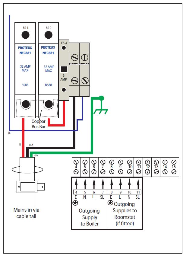
Before commencing check that the power source is in accordance with section 1.2 Site Requirements and ensure that it is isolated. Run the external wiring through the service slot provided in the base of the appliance. It is recommended that the 3 core input cable from the isolator to the appliance is not less than 1.5mm2 PVC grade to BS 6500. Clamp the cables in the grips provided below the terminal strip and ensure all cables are routed to avoid hot surfaces.
Note: The appliance is provided with a 4.0mm earth cable from an earthing strap on the primary return (to boiler) pipe to the earth stud on the wiring panel. 2.0 INSTALLATION
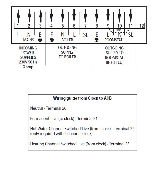
Make the connections as shown opposite on the terminal strip provided.
The appliance is provided with a link between terminals 9 and 11 on the terminal strip. This must be removed if a room thermostat is fitted see opposite.
No Clock Models
• If a remote clock is not being provided links will be required between 21/22 and 22/23.
• If a single remote clock is being provided a single link will be required between 21/22 to allow the appliance to provide hot water 24hrs/day.
• If a two channel clock is being provided no links will be required. (A two channel clock is normally only required to eliminate noise caused by the boiler fi ring during the night).
• Wire the connections from the clock as shown opposite.
Clamp the cables in the grips provided below the terminal strip and ensure all cables are routed to avoid hot surfaces.
Note: The appliance is provided with a 4.0mm earth cable from an earthing strap on the primary return (to boiler) pipe to the earth stud on the wiring panel.
INSTALLATION
The BoilerMate 2000 incorporates a pump overrun for the boiler pump and terminal 6 on the terminal strip (as shown on page 22) should only be used if the boiler requires a permanent live for another purpose.
The boiler manufacturers wiring instructions should be read in conjunction with this manual. Before switching on the electrical supply check all the factory made terminal connections to ensure they have not become loose during transit.
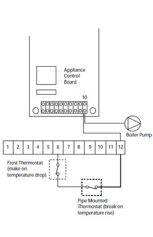
Frost Protection
When frost protection is required for the whole house or where a base temperature is required during cold weather, then a frost thermostat should be wired across plug in terminals 21 and 23 on the A.C.B board.
An alternative to fitting a frost thermost would be to set the programmer to constant during the time required and adjust the room thermostat to a suitable setting.
When frost protection is required for the boiler circuit only a frost thermostat and pipe mounted thermostat should be fitted. The pipe thermostat should be mounted on the primary return pipe adjacent to the boiler and both thermostats should be wired from the terminal strip as shown opposite.
INSTALLATION
WIRING DIAGRAM - BOILERMATE 2000 WITH SWITCH
INSTALLATION
WARNING: IF THE BOILERMATE IS FITTED WITH AN OPTIONAL ELECTRIC BACKUP SYSTEM I.E. ‘SWITCH’.
IMPORTANT: ELECTRICIAN/INSTALLER PLEASE NOTE.
THE 2 x 25A FUSES FOR THE ‘SWITCH’ ELECTRIC BACKUP SYSTEM ARE SUPPLIED IN THE ACTIVE FUSE CARRIER. THE GAS BOILER CAN BE COMMISSIONED WITHOUT INSERTING THESE FUSES.
IT IS IMPORTANT THAT THE GAS BOILER IS COMMISSIONED BEFORE TESTING OR USING EMERGENCY SWITCH FACILITY.
AFTER THE GAS BOILER HAS BEEN COMMISSIONED CUT AND REMOVE THE PLASTIC TIE AND PUSH DOWN FULLY THE CARRIAGE TO COMMISSION THE SWITCH FACILITY.
Electrical Power Supplies - BoilerMate 2000 with Switch.
A heavy duty electrical supply, see table on page 18, is required for this model and we recommend that a fully qualified electrician must undertake this work. The electrical installation must comply with the IEE Requirements for Electrical Installations BS 7671.
Note: do not attempt the electrical work unless you are competent to carry it out to the above standards.
A 10.0mm2 power cable is fitted with a 3 metretail for the installer to connect to a double pole linked isolator with a contact separation of 3mm in both poles which must not be more than 2 metres away from the appliance. A schematic arrangement of the internal wiring is shown on page 24. All terminals are labelled. Before commencing check that the power supply source (i.e. isolator) is in accordance with section 1.2 Site Requirements and ensure it is isolated. Run the 3 metretail through the service slot provided in the base of appliance. The recommendations contained under Electrical Connection - Standard Appliance should be followed when connecting a remote clock, room thermostat, boiler etc.
WARNING : DO NOT SWITCH ON ELECTRIC BACKUP, IF FITTED, UNTIL THE APPLIANCE HAS BEEN FULLY COMMISSIONED i.e. PRIMARY STORE IS FILLED AND VENTED.
INSTALLATION
COMMISSIONING
Open the incoming stop valve and fi ll the domestic mains cold and hot water systems. Fill the whole of the primary heating system with potable water through the feed and expansion cistern. Check the water level in the feed and expansion cistern and adjust the ballvalve if necessary. Check the whole of the primary heating and domestic hot and cold distribution systems for leaks. It is essential that all systems function properly for optimum performance.
To achieve this, the primary system should be commissioned in accordance with good practice and generally in accordance with the requirements of BS 6798, BS 5449 and BS 7593.
Full details of the requirements are given in PAS 33:1999 under Section 10 Commissioning.
When using either cleansing or corrosion inhibitor chemical, the manufacturers instructions must be followed.
Cleansing the Primary System
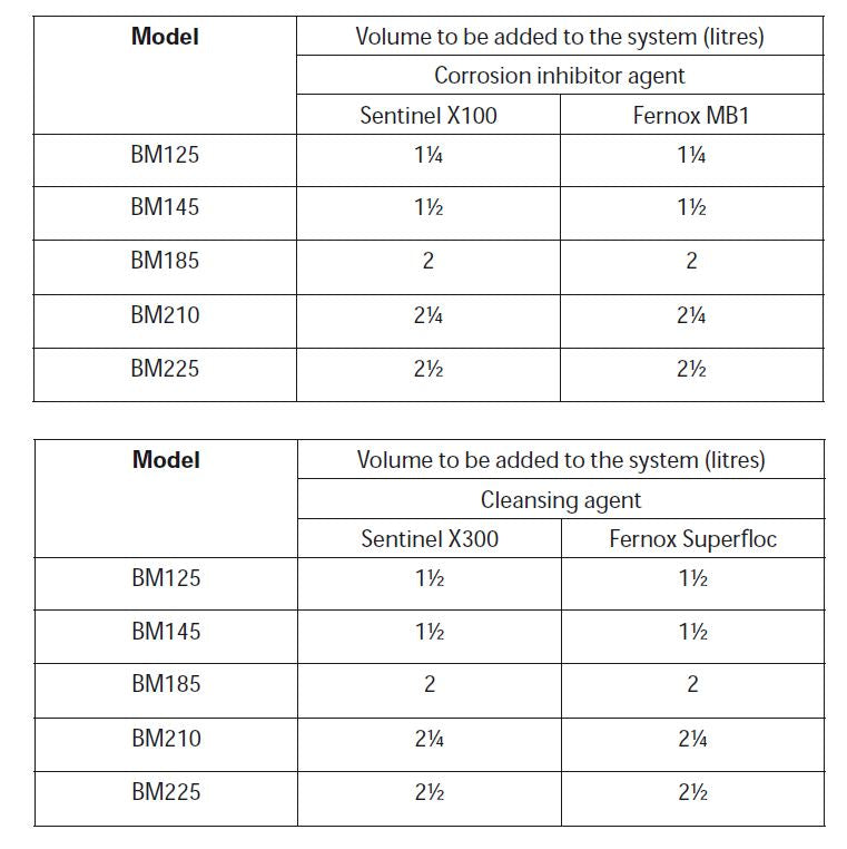
When determining the quantity of cleanser required, be sure to allow for the increased volume of water in the primary circuit due to the thermal store. In most cases the quantities shown opposite will be adequate for a typical 3/4 bedroom property.
Primary Water System Treatment
Although the BoilerMate 2000 has no special water treatment requirements, the radiators and other parts of the circuit will benefit from the application of a scale and corrosion inhibitor such as Sentinel X100 or a Protector such as Fernox MB1.
When determining the quantity of inhibitor required, be sure to allow for the increased volume of water in the primary circuit due to the thermal store - see section 1.2 Technical Data for volumes. In most cases the quantities shown opposite will be suitable for a typical 3/4 bed property.
POWERFLUSHING/CLEANING OF THE HEATING SYSTEM
If it is proposed to ‘powerflush’ the heating system we would recommend that the BoilerMate appliance is isolated from the heating system being cleaned. Failure to do this could seriously damage the appliance.
When carrying out the work always comply fully with the manufacturers instructions for the powerflushing equipment being used. If in any doubt please consult our Technical Helpline.
INSTALLATION
COMMISSIONING
Once the system is finally filled turn down the servicing valve for the ballvalve in the F & E cistern to the point where the warning/overflow will cope with the discharge arising from a ballvalve failure.
Cleansing Hot/Cold Water System Treatment
Fully flush and if necessary chlorinate the hot and cold water system in accordance with the recommendations in the Model Water Byelaws and BS 6700.
Commissioning the BoilerMate Control System
For maximum system efficiency the store thermostat must be in control of the boiler i.e. the boiler cycles on the store thermostat and not on its integral thermostat. The BoilerMate control system will automatically commission itself to match the actual performance of the installed boiler. The control system/A.C.B has been initialised at the factory and will operate automatically.
However, the operation of the control system should be checked as follows on the A.C.B (shown opposite).
1. Set the boiler thermostat to MAXIMUM
2. Switch off heating on the clock/ programmer and room thermostat
3. Switch off hot water on the programmer if 2 channel clock is fitted
4. Check the jumper settings are correct. These must all be in the correct positions for the appliance to work correctly i.e. fitted on terminals 1, 3 and 4. 5. Switch on the mains supply. The A.C.B. will automatically commission itself to suit the system/boiler and the dot after the ON the display will flash
The control system is now initialised. The operation of the controls can now be checked.
1. Horizontal LED bar 2 ‘store’ will be lit. Boiler and boiler pump will be running and green LED’s 1 and 2 on the A.C.B will be switched on.
INSTALLATION
Note: The controls within the A.C.B will not allow the heating system to function until the store temperature has reached 60°C. Therefore although the LED bar 1 ‘HT’ will light when heating is switched on, the heating pump (Green LED -3) will not switch on if the store temperature is less than 60°C. Time will need to be allowed for this to happen during initial commissioning. This will vary depending on the boiler size and the model of the BoilerMate 2000 being used.
2. Once a temperature of 60°C has been reached on the thermal store, switch on space heating clock/programmer and room thermostat. • Horizontal LED bar 1 ‘HT’ will light. • Green LED 3 on the A.C.B will switch on. Heating pump will run.
3. Switch off space heating on clock/programmer or room thermostat • Horizontal LED bar 1 ‘HT’ will switch off. • Green LED 3 on the A.C.B will switch off. Heating pump will switch off.
4. Open the hot tap • Horizontal LED bar 3 ‘HW’ on the LED display will light. • Domestic hot water pump will run.
5. Close the hot water tap • Horizontal LED bar 3 will switch off • Domestic hot water pump will continue to run for a short period of time before switching off.
6. The A.C.B incorporates a 3 minute pump overrun facility. Check green LED 2 remains lit for this period of time when the boiler switches off i.e. the thermal store reaches temperature.
The control functions have now been checked.
Let the boiler heat the store and when the store is satisfied, i.e. green LED’s 1 and 2 on the A.C.B are off, the radiator circuit and hot water can be checked and balanced in the normal way.
The boiler thermostat should be left at maximum for optimum performance/
efficiency.
When commissioning the system
• If the boiler is range rated, then adjust it to the maximum heat input.
• Check the boiler thermostat is set to maximum.
• Set the boiler pump speed so that the temperature difference across the boiler is about 8°C - when the space heating is off. NOTE: For optimum performance when using a condensing boiler such as the Keston C25 set the boiler pump in the BoilerMate to give about 15ºC temperature rise across the boiler.
• Set the heating system pump speed so that the temperature difference across the flow and return is not greater than 11°C.
• Check the DHW plate heat exchanger pump is set to maximum.
• Check that there is no overflow when the whole of the system is fully up to temperature.
• Check that the Y type strainer on the incoming mains cold water inlet to the appliance is clean.
Note: If the appliance is operating at mains cold water pressures below 1½ bar the flow regulator fitted on the outlet to the Y type strainer can be removed if required to improve performance.
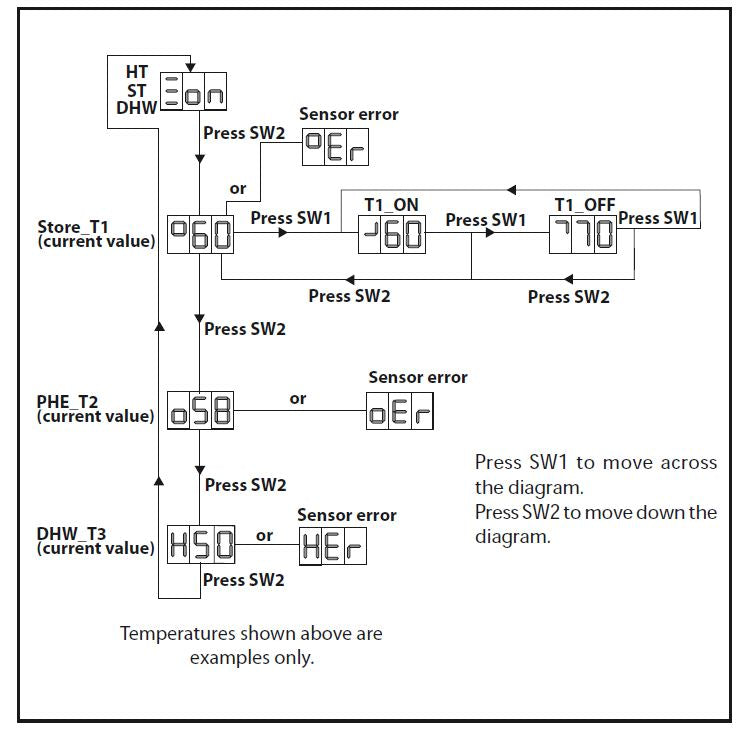
Because the A.C.B is able to adjust to suit the water temperatures delivered by the boiler the thermostat should always be set at maximum during commissioning. However, the boiler thermostat setting can be reduced in summer, in the normal way, if the appliance is being used for hot water only. The temperature settings established during commissioning can be checked using push button switches sw1 and sw2 on the PCB as described in section 3.3 Fault Finding.
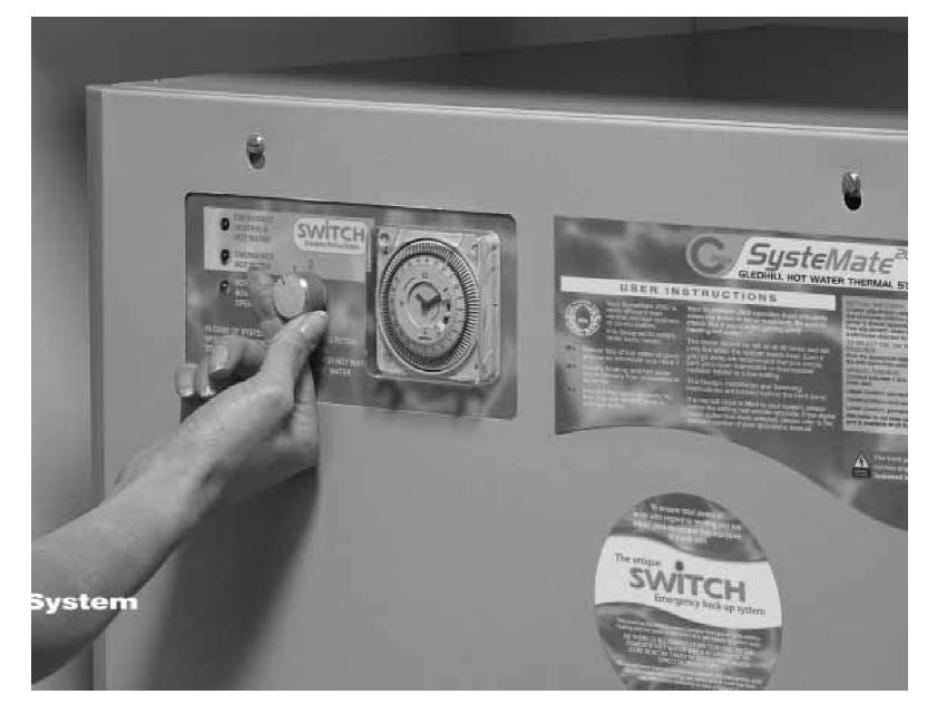
The clock/programmer provided on the appliance controls the heating system only and should be set to suit the householders requirements using the instructions shown on the separate leaflet and the label on the front of the appliance. If the appliance is fitted with Switch (see figure on page 25) the boiler should be switched off and Switch operated to ensure it is working correctly.
• When the selector knob is not in normal position, the PCB, room thermostat and the time clock are electrically isolated.
• When the selector knob is in HW only position the plate heat exchanger pump will run continuously at full speed.
• When the selector knob is in the HW and HTG position, the plate heat exchanger pump and the heating pump will run continuously.
This product is covered by the ‘Benchmark’ scheme and a separate commissioning/ service log book is included with this product. This must be completed during commissioning and left with the product to meet the Warranty conditions offered by Gledhill.
On completion:-
1. Do ensure that the electrical connection (e.g. mains supply, room thermostat) to the unit is correct and tight before starting the commissioning procedure.
2. Do ensure that the functioning and control of the system is explained to the occupant.
These Instructions should be placed along with the component manufacturers instructions in the pocket provided on the rear of the front panel. The front panel should then be refitted.
INSTALLATION
Important Do’s and Don’ts
1. DO check the incoming mains water pressure and flow rate are adequate. (The preferred range of mains pressure is 2-3bar).
2. DO check that all connections are in accordance with the labelling on the thermal store.
3. DO adjust the ballvalve so that the water level in the F & E cistern when the system is cold is correct and does not overflow when the whole of the system is at maximum temperature.
4. DO make sure that there is adequate clearance above the F & E cistern to service the ballvalve.
5. DO ensure that the range rated appliances are set at the highest output and the boiler thermostat is set to maximum for all boilers.
6. DO ensure that the water level in the F & E cistern is at least 250mm above the highest point on the radiator circuit or the highest point of the system.
7. DO insulate any exposed pipework in the BoilerMate cupboard.
8. DO plumb the overflow/warning pipe in a 20mm internal diameter pipe material which is suitable for use with a heating F & E cistern, in accordance with BS 5449 (such as copper) and ensure it has a continuous fall and discharges in a conspicuous external position.
9. DO check the pump settings a. The boiler pump should be set to give a temperature difference across the boiler of 8°C or less. b. The heating pump should be set to give a temperature difference across the flow and return of not more than 11°C. c. The hot water plate heat exchanger pump should be set at maximum.
10. DO ensure that the bypass valve for the heating system (if fitted) is set correctly.
11. DON’T use a combined feed and vent on BoilerMate installations.
12. DON’T use a BoilerMate on a sealed primary i.e. closed system.
13. DON’T use pipe smaller than 28mm between the boiler and the BoilerMate when the boiler rating exceeds 20kW (about 68,000 Btu/h).
14. DON’T use dipped flow and return between the boiler and the BoilerMate unless the boiler is fitted with an overheat thermostat. If necessary check with the suppliers of the boiler.
15. DON’T operate the ‘switch’ backup facility until the system is fully fitted, vented and commissioned.
16. DON’T place any clothing or other combustible materials against or on top of this appliance.
SERVICING
ANNUAL SERVICING
No annual servicing of the BoilerMate 2000 is necessary.
However, if required, the operation of the controls and a hot water performance test can be carried out when servicing the boiler to prove the appliance is working satisfactorily and within its specification.
CHANGING COMPONENTS
Free of charge replacements for any faulty components are available from Gledhill during the in-warranty period (normally 12 months).
After this, spares can be obtained direct from Gledhill using the ‘Speed Spares’ service, or through any of the larger plumbers merchants/ specialist heating spares suppliers. Help and advice is also available from the Technical Helpline on 08449 310000. However, all components are readily accessible and can be changed quickly and easily by the installer using common plumbing practice.
If it is necessary to replace any of the pumps fitted to the appliance the pump head (motor pack) only should be removed as recommended by Grundfos. Assuming it is within warranty this will be accepted by a merchant as being covered by the Grundfos national service exchange agreement, as long as it is a complete pump i.e. alleged faulty motor pack and new base is left with the merchant. It is important when a pump has been replaced to ensure that any air is adequately vented.
SERVICING
SHORTS PART LIST
SERVICING
 SERVICING
FAULT FINDING
Despite everyones best efforts some problems could occur and lead to complaints from the householder.
Complaints can be grouped into the following three main categories:-
1. The system is noisy
2. Hot water service is unsatisfactory
3. Space heating is unsatisfactory
The following checks should be carried out by the installer before calling the
manufacturer.
1. Causes of a ‘Noisy’ System
Noisy pump operation
Check the level of water in the F & E cistern - adjust and vent the pump/system if necessary.
Check the pump speed setting of the boiler pump - reduce if necessary but ensure that the temperature rise across the boiler does not exceed 8°C.
Check the pump speed setting of the heating pump - reduce if necessary but ensure a temperature difference across the flow and return does not exceed 11°C.
Check and adjust if necessary the heating system bypass valve.
Check that the radiators are correctly balanced.
Noisy boiler operation
Check the flow rate through the boiler at full gas rate by measuring the temperature rise across the boiler. If the temperature rise is greater than 8°C, then increase the pump speed.
Check the level of water in the F & E cistern and the working head on the boiler.
Check and vent the system if necessary.
Noise when hot water tap is opened If the plate heat exchanger pump is noisy when the hot water tap is opened, then check the level of water in the F & E cistern and vent the pump if necessary. Water hammer - loose pipework and/or tap washers.
2. Causes of ‘Unsatisfactory Hot Water Service’
Check that the BoilerMate is full of water i.e. level of water in the F & E cistern is correct when system is cold.
Check boiler thermostat - this should be set at maximum.
Check that the boiler fl ow temperature is adequate when it stops fi ring. Boilers should provide a fl ow temperature of 82 ± 3°C but temperatures as low as 76°C will allow the BoilerMate 2000 to provide a satisfactory performance.
Check that the store is charging to at least 75°C.
Check that the hot water plate heat exchanger pump stops and starts when the hot water tap is opened and closed.
Check that the plate heat exchanger pump is set at maximum speed.
Check that the space heating and hot water load is not greater than the boiler output and that the BoilerMate 2000 model is suitable for the type of dwelling. If all the above checks are satisfactory then it is possible that the performance of the heat exchanger is impaired by scale. In this case the hot water flow rate will be noticeably less than the cold water flow rate. Replace with a factory exchange unit and re-check hot water performance.
3. Causes of ‘Unsatisfactory Space Heating’
Check the boiler thermostat - this should be set at maximum.
Check that the boiler flow temperature before it is switched off by its own internal thermostat or the store sensor is adequate - it should not be less than 80°C.
Check the operation and the settings of the heating programmer and the room thermostat.
Check that the heating system pump is circulating the water to the radiator circuit. If some rooms are not being heated properly, then balance the system/check the operation of the thermostatic radiator valves (if fitted).
Overflow from Feed and Expansion Cistern
Check that the controlled level of water in thecistern is no higher than necessary. Adjust if required.
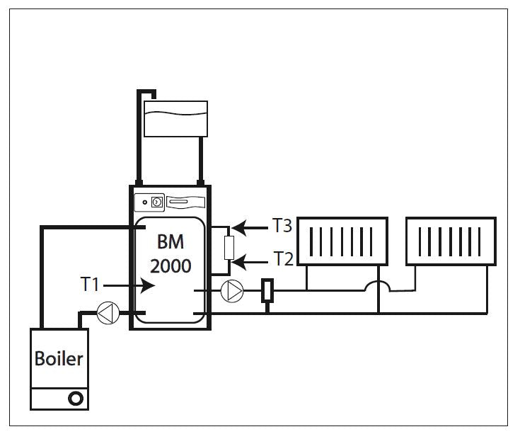
The ACB can be used to establish/check the operating and set temperatures of the appliance as well as identify faults on any of the 3 sensors. This is done by operating switches SW1 and SW2 as shown opposite and reading the LED display. (See page 27) Store T1, PHE T2, and DHW T3 indicate the current value being read by the store, PHE and DHW sensors respectively. The location of the sensors is shown in the diagram shown opposite/below.
T1 ON and T1 OFF show the store temperature set points which are automatically reset on each boiler cycle to match the temperature produced by the boiler.
T1 ON shows the temperature at which the store will call for heat, i.e signal the boiler to fi re. T2 OFF shows the temperature at which the store will be satisfied, i.e signal the boiler to switch off.
POWERFLUSHING/CLEANING OF THE HEATING SYSTEM
If it is proposed to ‘powerfl ush’ the heating system we would recommend that the BoilerMate appliance is isolated from the heating system being cleaned. Failure to do this could seriously damage the appliance. When carrying out the work always comply fully with the manufacturers instructions for the powerfl ushing equipment being used. If in any doubt please consult our Technical Helpline.
SERVICING
In addition to the main LED display the ACB has four green LED’S which can be used to check a supply is being provided when required to the Boiler (LED 1), Boiler pump (LED 2) and Heating pump (LED 3). LED 4 is not used on this appliance. The following procedure should be followed to carry out these checks.
• Switch off mains
• Check and if necessary insert correct jumpers 1, 3 & 4) to suit appliance type
• Insert jumper 5
• Switch on mains
• The PCB will carry out functional checks and then stop
• Switch off mains
• Remove jumper 5
• Switch on mains to put into normal operating mode
During the functional checks the green LED’s 1-4 will be switched on and then off at 5 second intervals.
Note: If the A.C.B. board is replaced it will re-initialize itself automatically.
The operation of the system controls/ operation can then be checked.
The same appliance control board is used on a number of appliances and the jumpers MUST be in the correct position for the appliance to work satisfactorily.
See section 2.3 Commissioning for details
If the problem cannot be resolved and the appliance is fitted with the switch emergency electric backup this should be switched on and operated in accordance with the instructions on the label fitted to the appliance until the installer/manufacturer can attend. When requesting a visit from the manufacturer the installer must have the completed ‘Benchmark’ commissioning/ service record sheet to hand to enable help to be provided.
APPENDIX A
WATER SAVINGS
WATER RELATED COSTS CAN BE REDUCED BY GOOD PLUMBING PRACTICE.
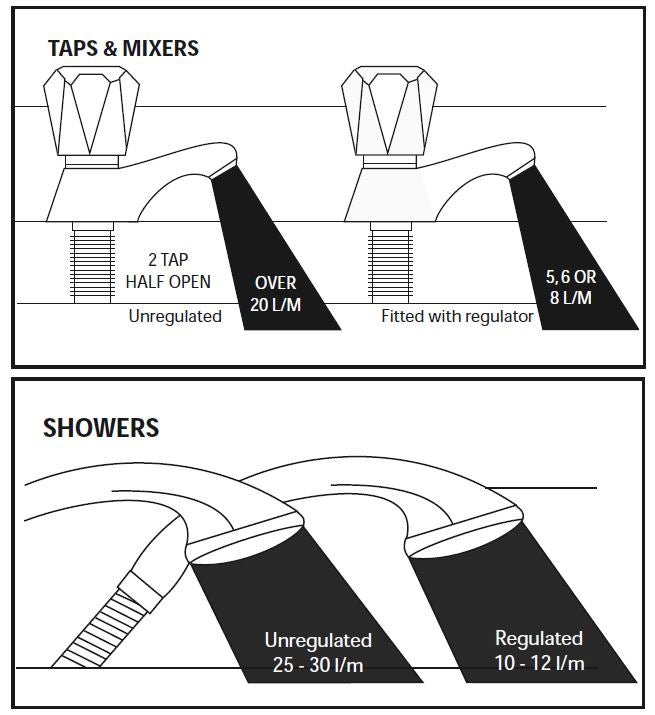
Vast quantities of water are needlessly run off to waste due to Taps, Mixers and Showers discharging flow rates far in excess of the rates required for them to perform their duties. The contrasting flow rates shown on this leaflet clearly illustrate the savings that can be made whilst still providing a good performance. British made Aquaflow Regulators provide constant flow rates by automatically compensating for supply pressure changes between 1 bar & 10 bars. To facilitate installation into the wide range of plumbing equipment which is encountered in the U.K, Four Fixing Options are available:-
OPTIONS FOR SHOWERS
1. MXF “DW” Range - For fitting behind Fixed Shower Heads or onto Flexible Hoses for Handshowers (preferably onto the inlet end when lightweight hoses are used).
2. Compression Fitting Range. “In Line” regulators as in Option 4 for Taps & Mixers.
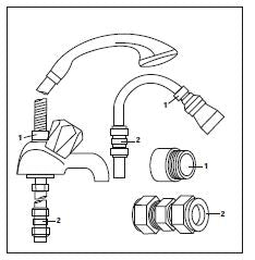
4 FIXING OPTIONS FOR TAPS &
MIXERS
1. MK Range - Combined Regulators & Aerator for screwing onto Taps & Mixers with internal or external threads on their noses. Anti Vandal models also available.
2. MR05-T Range - Internal Regulators. Push-fi t into Tap or Mixer seats. Produced in three sizes - 12.5mm (BS1010), 12mm & 10mm, Flangeless models also available for Taps with Low Lift washers.
3. MXF Standard Range - Screw on tail models for Taps & Mixers. Fix onto the tails before fitting the tap connectors. Available in 3/8", 1/2", 3/4" and 1" BSP.
4. Compression Fitting Range - “In Line” regulators housed in 15mm & 22mm CXC Couplers & Isolating Valves. “ ”UK WFBS listed by the Water Research Centre. Isolation valves available for slotted screwdriver operation or with coloured plastic handles. Now available also in plastic bodied push-fi t couplers & valves.
APPENDIX B
MANIFOLDS
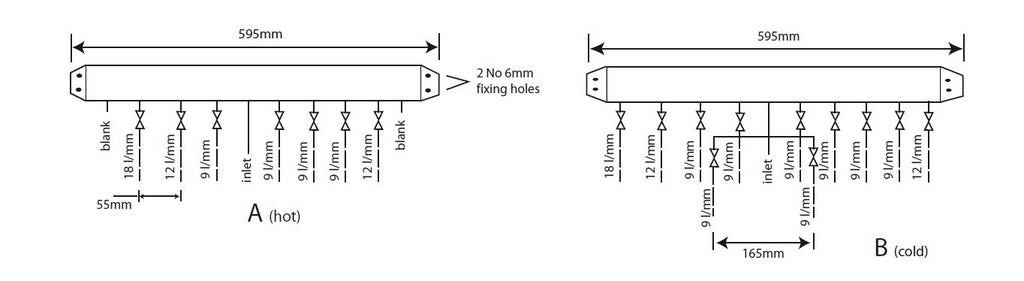
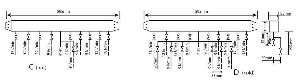
Two sets of manifolds are available as an optional extra. Each set comprises a separate hot and cold water manifold. Both are provided with a 22mm inlet connection located centrally. All outlet connections are 15mm compression. The centre to centre dimension of each branch is 55mm.
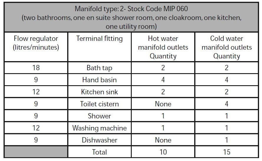
The arrangement of each manifold is supplied as shown. This provides the best balance of flows but the flow regulators/duty of each branch can be changed if required as long as a reasonable balance is maintained. If it is necessary to change or clean the flow regulator this can be done without needing to drain the system by closing the valve and removing the screwed cover below the white plastic cover.
The manifolds are designed to be used with plastic pipework and are supplied complete with isolation valves and flow regulators on each branch. They would normally be installed in the same cupboard as the thermal storage appliance (as shown below) but can be installed in another cupboard close to the appliance if required.
APPENDIX B
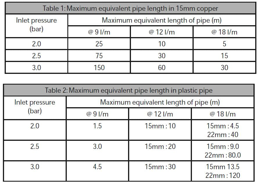
The pressure loss through a flow regulator at the designated flow rate is about 1.8 bar. Therefore for the flow regulator to control the flow rate at pre-set level, the inlet pressure must be greater than 1.8 bar. If the inlet pressure is lower, the flow rate will be correspondingly less than the pre-set values.
The maximum equivalent pipe lengths from the manifold to the terminal fi ttings can be estimated from the above information and the resistance characteristics of the pipes. The examples presented below are for 15mm copper pipe in table 1 and for plastic pipework in table 2.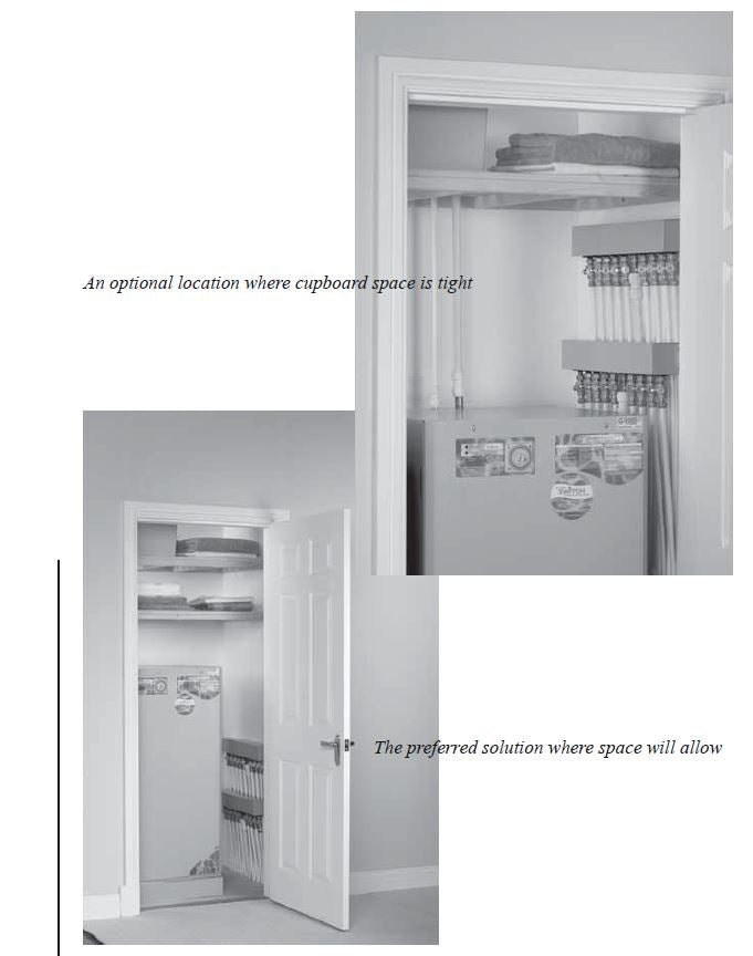
APPENDIX B
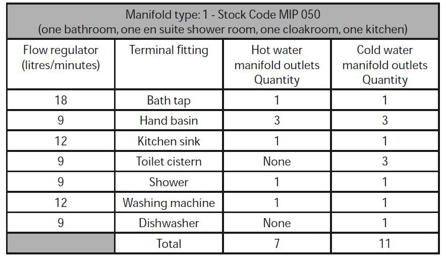
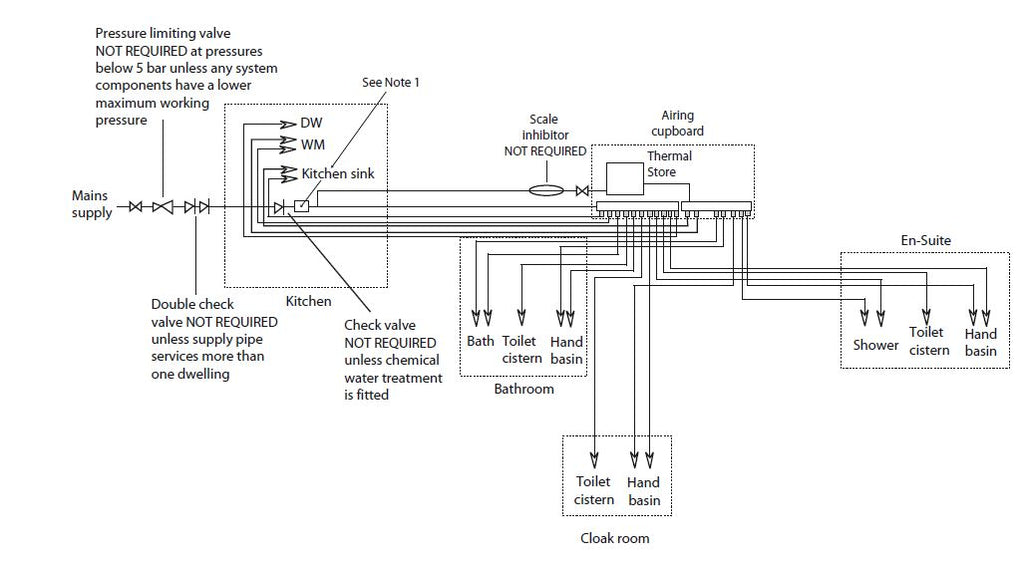
The size of the distribution pipes supplying the manifold should be calculated using the method set out in BS 6700. A typical diagrammatic arrangement of a system using Manifold Type 1 is shown below. This is only meant to show the principles involved and the actual connection of fittings to the manifold will need to suit the arrangements shown on page 35.
Note 1 - If it is proposed to fi t chemical water treatment such as a water softener this should be fitted in this location and the cold water branch in the sink should be branched off the cold water main prior to the treatment device instead of the cold water manifold.
Any other isolating/control valves and backflow protection devices should be provided as necessary to comply with the Water Regulations.
APPENDIX C