BoilerMate 3
For Gledhill BoilerMate 3 Parts and Spares click on the following links: Gledhill BoilerMate 3 Parts And Spares
An open vented central heating and mains pressure hot water supply system incorporating a thermal store
Design, Installation and Servicing Instructions
ALL MODELS COMPLY WITH THE WATER HEATER MANUFACTURERS SPECIFICATION FOR INTEGRATED THERMAL STORES.
CONTENTS
GLEDHILL BOILERMATE Ill SPECIFICATION
| Section | Details |
| 01 | DESCRIPTION |
| 02 | SYSTEM DESIGN |
| 03 | INSTALLATION |
| 04 | COMMISSIONING |
| 05 | FAULT FINDING/DIAGNOS TICS |
| 06 | APPENDICES |
| 07 | SPARE PARTS LIST |
| 08 | SALE & WARRANTY TERMS |
These instructions should be read in conjunction with the installation and servicing instructions issued by the manufacturer of the heat source e.g. the boiler used. Any water distribution and central heating installation must comply with the relevant recommendations of the Regulations and British Standards listed below.-
Regulations
• Gas Safety Regulations
• Building Regulations
• I.E.E Wiring Regulations
• Bylaws of the Local Water Undertaking
British Standards
886798, 885449, 885546, 885440:1, BS5440:2, CP331 :3, 886700, BS5258 and 887593:1992
A competent person as stated in the Gas Safety Regulations must install the BoilerMate heating system. The manufacturer's notes must not be take asoverriding statutory obligations.
The BoilerMate Ill is not covered by section G3 of the current Building Regulations and is therefore not notifiable to Building Control.
Although the domestic water supply to the BoilerMate Ill is at mains pressure, it is not necessary to fit an expansion vessel, pressure or temperature relief valve.
The BoilerMate Ill is only suitable for use with an open vented primary i.e. central heating system.
The information in this manual is provided to assist generally in the selection of equipment. The responsibility for the selection and specification of the equipment must however remain that of the customer and any designers or consultants concerned with the design and installation.
Please Note: We do not therefore accept any responsibility for matters of design, selection or specification or for the effectiveness of an installation containing one of our products.
All goods are sold subject to our Conditions of Sale, which are set out at the rear of this manual.
In the interest of continuously improving the BoilerMate range, Gledhill Water Storage Ltd reserve the right to modify the product without notice, and in these circumstances this document, which is accurate at the time of printing, should be disregarded.
The Gledhill BoilerMate range is a WBS listed product developed in conjunction with British Gas.
This product is manufactured under a BS EN 1509002 Quality System audited by BSI
DESCRIPTION
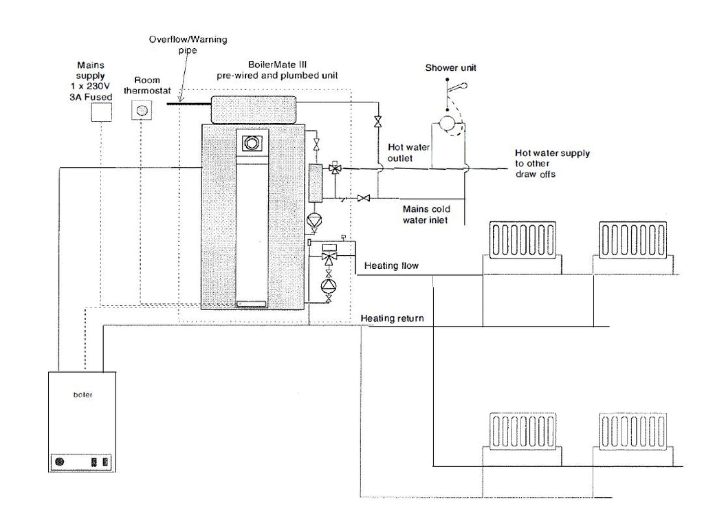
TYPICAL SCHEMATIC OF BOILERMATE Ill SYSTEM FIGURE 1.1
DESCRIPTION
Introduction
The BoilerMate Ill shown schematically in Figure 1.1, is designed and used to provide improved space heating as well as a mains pressure hot water supply system with any remotely sited boiler. A report by the Cranfield Institute o!Technology found that heat storage systems give a potential for energy savings of between 5% and 15%.
The principle of a BoilerMate Ill is to separate the heat generator e.g. a boiler from heat emitters by a thermal store, which evens out the fluctuating demands for heating and hot water. Thus by storing energy produced when the demand is low and discharging it when the demand is high (i.e. during warm up or when hot water is drawn off), a smaller boiler can be used.
An important feature of this concept is that hot water can be supplied directly from the mains at conventional flow rates without the need for temperature and pressure relief safety valves or expansion vessels. This is achieved by passing the mains water through a plate heat exchanger. The outlet temperature of the domestic hot water is maintained by a printed circuit board, which controls the speed of the pump circulating the primary water from the store through the plate heat exchanger.
Any automatic boiler of up to a maximum of 30kW (about 100,000BTU) can be linked to any suitable model of BoilerMate Ill (see Table 1.1, page 7) and the deciding factor is the space heating and the hot water requirements of a dwelling.
THERMAL STORE
The copper thermal store contains primary water, which is maintained at a temperature close to the maximum boiler flow temperature in winter.
DOMESTIC HOT WATER
Cold Water Supply
The BoilerMate Ill units are designed to be fed directly from the mains water supply as shown schematically in Figure 1.2. They fulfil the requirements of Water Bylaw 91, and therefore do not require a check valve to be fitted to the supply pipe.
The performance of the BoilerMate Ill is directly related to the adequacy of the cold water supply to the dwelling. This must be capable of providing for those services, which could be required to be supplied simultaneously, and this maximum demand should be calculated using procedures defined in 886700.
BoilerMate will operate at pressures as low as 1 bar and this must be available when the local demand is at its maximum, but the preferred range is between 2 and 3 bar.
As a general guideline, although a 15mm external service may be sufficient for smaller dwellings with one bathroom, a 22mm service (25mm MOPE) is preferred and should be the minimum for larger dwellings.
If a water meter is fitted in the service pipe, it should have a nominal rating to match the maximum hot and cold water peak demand calculated in accordance with BS 6700. This could be up to 50l/min in some properties.
The unit must be fitted strictly in accordance with the requirements of the Local Water Undertaking who should be consulted prior to the installation. In the event of any difficulty please contact us as the manufacturers.
The equipment used in the system should be suitable for a working pressure of 8 bar and approved by the WBS or other relevant standard. If this is not the case a pressure limiting valve will be required which is suitable for the items of equipment with the lowest maximum working pressure.
We recommend that a lockshield pattern gate valve is fitted on the cold inlet to the appliance. This can be used for isolating/maintenance purposes or in areas of high pressure can be used to control the flow through the appliance to 30 litres/minute.
Safety Fittings
It is not necessary to fit control and safety equipment normally associated with mains pressure hot water storage appliances e.g. temperature and pressure relief valves and expansion vessel. BoilerMate Ill is WBS listed and a non-return valve is not required. However if the ancillary equipment fitted in the supply to these appliances require a non-return valve then the valve must be fitted directly after the branch to the drinking water i.e. a kitchen sink as shown schematically in Figure 1.2.
Domestic Hot Water Flow Rates
Provided the pipe sizing and the supply pressure is adequate the hot water flow rate should be up to 351/ min. for all models (see Table 1.1 ). The domestic hot water outlet temperature is regulated to approximately 52°C by the electronic control system and is not user adjustable. However different factory settings are available for special applications eg. old peoples homes.
Use in Hard Water Areas
There are two options for the pump speed control. Option 'H' must be used in hard water areas above 200ppm. Option 'S' can be used in soft water areas below 200ppm. A patented control system within the Option 'H' microprocessor offers a more sophisicated level of pump speed control and will help prevent the formation of scale. Both options ('H' or'S') prevent domestic hot water from exceeding 55°C for most of the operational times of the appliance.
It is not necessary to fit any form of scale inhibiting equipment in the domestic cold water supply to the BoilerMate when using option 'H'. If scale should, become a problem the plate heat exchanger is easily isolated and can be replaced with a service exchange unit.

DESCRIPTION
Mounted in the front panel are two printed circuit boards: one for pump speed control of Domestic Hot Water, the other for wiring all system components (see diagram on page 18).

CONTROL

PACKAGED CONTROL SYSTEM
Standard Equipment
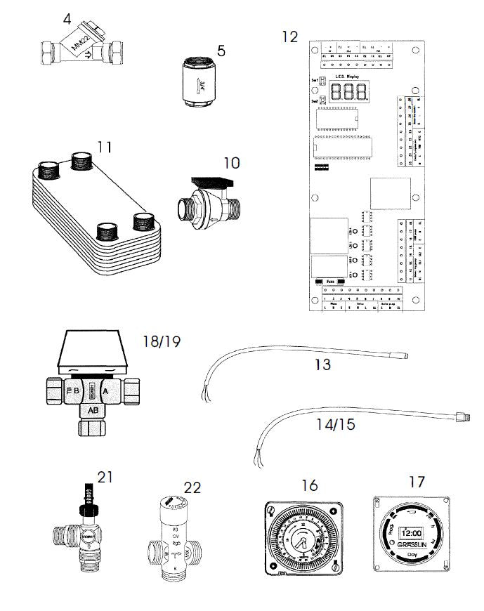
The standard configuration of the BoilerMate Ill is shown in Figure 1.3. The two printed circuit boards mounted inside the appliance control the operation of the complete system. The system control PCB also acts as the wiring centre for the components. The connection arrangement of the BoilerMate Ill is shown in Figure 1.4. It is supplied with the following factory fitted equipment:
1.Boiler/space heating system pump
2.Domestic hot water primary (plate heat exchanger) pump3. Automatic heating system bypass valve
4. Appliance control board (ACB)
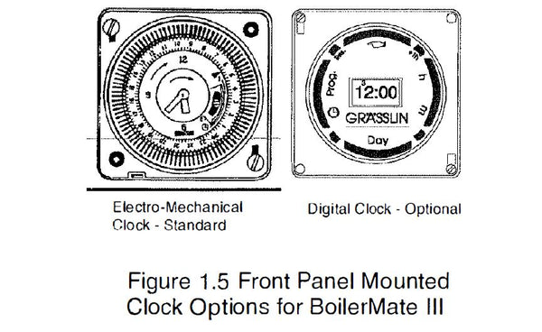
5. 3-Port flow share valve6. Electro-mechanical clock (Figure 1.5) to control the space heating (in conjunction with room thermostat if fitted).
7. Plate heat exchanger.
8. DHWS flow switch.
9. DHWS temperature sensor.
10. DHW mixing valve.
11 . Y type strainer.
DESCRIPTION
Optional Equipment
• A seven-day digital clock/programmer (Figure 1.5) to control the space heating (in conjunction with a room thermostat if fitted).
• A kit to site the clock/programmers shown in Figure 1 .5 remotely.
• A no clock option - to be used with any two channel clock for controlling both the operation of the space heating (in conjunction with a room thermostat if fitted) and the charging of the thermal store.
ELECTRIC IMMERSION HEATER
If an electric immersion heater is fitted then it must:
1 . Be set to operate at 75°C
2. Be wired to a separate 13A fused and switchable power supply.
3. Not be wired into any of the terminals on the appliance printed circuit boards.
This can be supplied at the time of order as an extra. Replacement immersion heaters should be obtained only from Gledhill Water Storage Ltd.
TECHNICA L SPECIFICATION
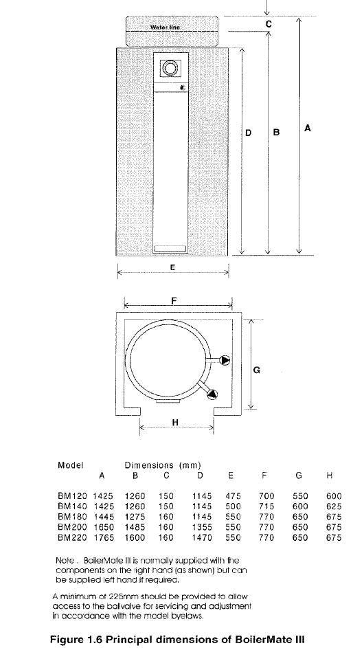
The principal dimensions of the BoilerMate Ill model range are shown in Figure 1.6 and the technical specification of the units is given in Table 1 .1.
DESCRIPTIONS

NOTES:
1. The flow rates are for 35°C average temperature rise and assume normal pressure and adequate flow to the appliance.
2. All units are supplied complete with an integral feed and expansion cistern. This is easily removed from animodel and repositioned remotely up to maximum of 6m above the base of the store if necessary.
3. The feed and expansion cistern will fit in any space greater than 530mm high by 500mm square which includes the necessary allowance for ballvalve servicing.
4. Any pattern BoilerMate Ill can be specified 'ET' for use with dual boilers e.g. gas and solid fuel.
5. With integrated thermal storage, it is important to note that hot water and heating loads can be supplied simultaneously.
6. All BoilerMate Ill's meet the appropriate requirements of the WMA Specification for Integrated Thermal Stores.
7. For hard water areas use suffix 'H', for soft water areas use suffix 'S' after the model number, e.g. BM120H = BoilerMate Ill model 120 for hard water area.
8. Non standard sizes are available to suit smaller cupboard dimensions.
9. 28mm 3 Port valve and primary connections and/or a Grundfos 15/60 system pump can be provided for the 120, 140 and 180 models at additional cost.
10. All BoilerMate models can be provided for a 1 Om working head.
SYSTEM DESIGN
The efficiency of this system is such that special design criteria apply when calculating the boiler size. It is only necessary to calculate the heating requirements in accordance with BS 5449 and add the following allowances for hot water, which are approximately half the traditional allowances.
Up to 1 bathroom and 1 shower : 1 .5kW
Up to 2 bathrooms and 2 showers: 3.0kW
Up to 3 bathrooms and 3 showers : 4.0kW
The primary pipework connecting the boiler and the thermal store should be sized to achieve a maximum of 10°C rise across the boiler or the maximum temperature rise specified by the boiler manufacturer, whichever is smaller but in any instance it should not be less than 22mm copper tube.
Note: There should be no valves in the pipework connecting the boiler to the BoilerMate Ill.
The heating circuit operates on the normal primary boiler temperatures i.e. 82°C flow and 71°C return. Therefore any traditional hot water radiators or convectors can be used with this system and no special over-sizing of the heat emitters is necessary.
The BoilerMate 111 is supplied as a factory fitted and prewired package consisting of:
1. Boiler/space heating pump
2 . Domestic hot water primary pump
3. Automatic heating bypass valve
4. Appliance control board (ACB)
5. 3-Port flow share valve
6. Electro-mechanical clock to control the space heating (in conjunction with room thermostat if fitted).
7. Plate heat exchanger.
8. DHWS flow switch.
9. DHWS temperature sensor.
10. DHW mixing valve.
11. Y type strainer.
SYSTEM DESIGN
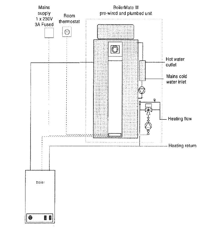
Boiler Sited Below BoilerMate Ill
Any boiler can be used when the flow pipe from the boiler to the BoilerMate Ill rises continuously. No part of the flow pipe should contain a valve or other device (which can be accidentally closed), as this forms the safety open vent should the boiler thermostat fail.
Boiler must be fitted with overheat thermostat. The F & E cistern must be fitted at a height which will provide the minimum head required for the boiler.

SYSTEM DESIGN
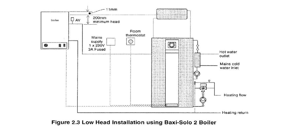
Boiler with Dipped Flow & Return Pipes to BOILER Mate Ill
If the flow and return pipes between the boiler and the BoilerMate Ill are dipped, then the boiler must be fitted with an over-heat thermostat. In these circumstances the automatic air vents should be fitted as shown in Figure 2.2.
In situations where the headroom is restricted (e.g. in a flat), the boiler manufacturer's instructions with regard to minimum head must be followed. For example, a 'Baxi Solo 2' boiler may be installed in accordance with Figure 2.3. The feed and expansion cistern may be left attached to the store and the whole BoilerMate Ill raised on a platform to give the required working head.
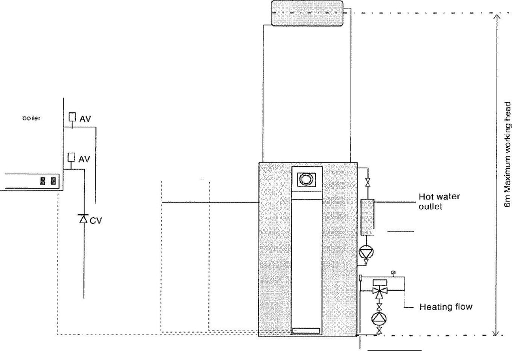
Boiler Sited above BoilerMate 111
If the boiler is above the BoilerMate Ill as shown in Figure 2.4, the F&E cistern can be detached from the BoilerMate Ill and sited at a higher level to give at least the minimum working head required for the boiler. However the height of the water level in the F&E cistern from the base of the store should be no greater than 6m. In this system configuration a gravity check valve is necessary as shown in Figure 2.4 to prevent gravity circulation between the BoilerMate Ill and the boiler during dormant periods.
SYSTEM DESIGN
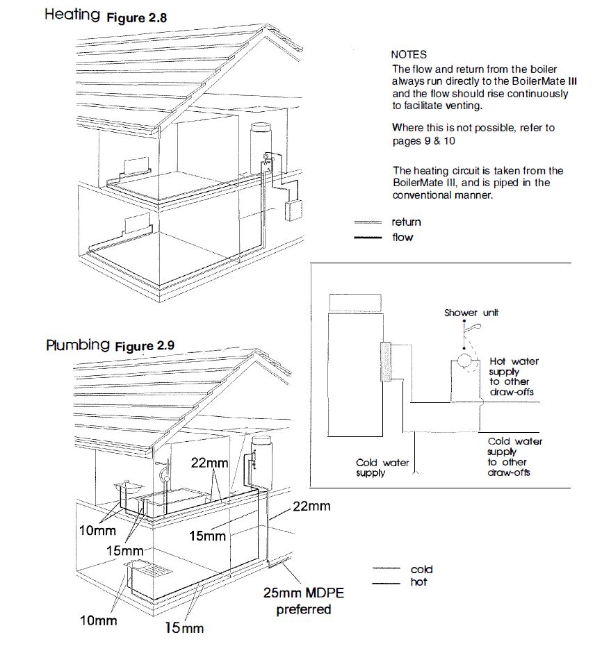
Heating System
A schematic layout of the heating system in a typical small dwelling is shown in Figure 2.8.
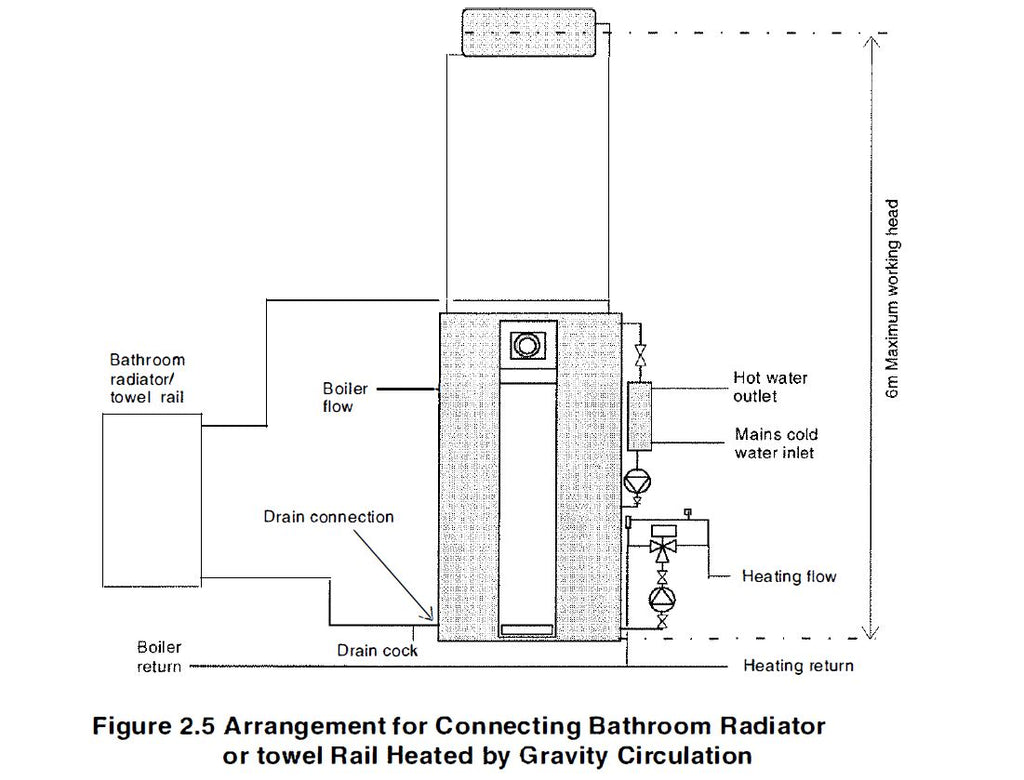
1. If heating of a bathroom radiator or towel rail is required in summer, then it can be piped as a gravity circuit shown schematically in Figure 2.5. The flow pipe to the radiator can be teed into the safety open vent pipe and the return pipe from the radiator can be connected to the store drain connection and the drain moved to the return pipe.
2. If the boiler is fitted at a higher level than a BoilerMate Ill then it may be necessary to fit a gravity check valve in the primary circuit to prevent reverse circulation during dormant periods.
3. All units come complete with their own feed and expansion cistern. The water level in this tank should be at least 250mm above the highest point on the system including the radiators.
4. The BoilerMate Ill is only suitable for an open system. The F & E cistern may be detached from the unit and fitted remotely up to 6m above the base of the BoilerMate Ill i.e. the maximum static pressure in the store must not exceed 0.6bar.
5. The overflow /warning pipe should be installed in material suitable for heating system feed and expansion cisterns in accordance with BS 5449.
SYSTEM DESIGN
6. An automatic bypass is fitted on the BoilerMate Ill to compensate for pressure (i.e. flow rate) changes in the heating circuit e.g. when the thermostatic radiator valves close. The system does not require any other bypass valves.
7. The performance characteristics of the system pumps is given in Figures 2.6 and 2.6a.

COUPLING GAS AND SOLID FUEL BOILERS TO BOILER MATE
Existing or new solid fuel open fires with a back boiler or a solid fuel boiler can be connected to the BoilerMate Ill, however if required please discuss this with our Technical Department.
SYSTEM DESIGN
HOT AND COLD WATER SERVICES
A schematic layout of the hot and cold water services in a typical small dwelling is shown in Figure 2.9. BoilerMate Ill will operate at mains pressures as low as 1 bar and as high as 8 bar although the preferred range is 2-3 bar. It is also important to check that all other equipment and components in the hot and cold water system are capable of accepting the mains pressure available to the property. If the mains pressure can rise above the maximum working pressure of any item of equipment or component to be fitted in the system a suitable pressure limiting (reducing) valve will be required.
Taps and Valves
1. Aerated taps are recommended to prevent splashing.
Pipe Sizing
To achieve even distribution of the available supply of hot and cold water, it is important in any mains pressure system that the piping in a dwelling should be sized in accordance with BS6700. This is particularly important in a large property with more than one bathroom. However the following rule of thumb guide lines should be adequate for most typical property types: -
1. A 15mm copper or equivalent external service may be sufficient for a small 1 bathroom dwelling (depending upon the flow rate available), but the minimum size for larger dwellings must be 22mm (25mm MDPE).
2. The internal cold feed from the main incoming stop tap to the BoilerMate should be run in 22mm pipe. The hot draw-off should also be run in 22mm as far as the branch to the bath tap.
3. The final branches to the hand basins and sinks should be in 10mm and to the shower in 15mm.
4 . The final branches to taps i n existing properties, which are in 15mm, should be restricted to balance the flow to each outlet.
5. We would recommend that best results for a balanced system are achieved by fitting appropriate flow regulators to each hot and cold outlet (see Appendix).
6. For properties where the inlet pressure is high and the flow rates may exceed 30 L/min at any bath hot tap the installer must fit a lockshield pattern gate valve at the cold inlet to the appliance. This should then be adjusted to restrict the maximum flow rate to 30 Umin.
Showers
1 . Any type of shower mixing valve can be used as long as both the hot and cold supplies are mains fed. However, PRESSURE COMPENSATING shower mixing valves are proven to give better control when more than one fitting are open simultaneously and are therefore STRONGLY RECOMMENDED. Thermostatic versions are preferable.
2. The hot water supply to a shower mixing valve should be fed wherever practical directly from the BoilerMate Ill or be the first draw-off point on the hot circuit.
3. The cold supply to a shower mixing valve should be fed directly from the rising mains via an independent branch.
4. Fixed head type showers: No back-syphonage arrangements are necessary.
Bidets
1. The supply of hot and cold mains water directly to a bidet is permitted provided that it is of the over-rim flushing type a n d that a type 'A' air gap is incorporated.
2. It must not include either an ascending spray or provision to attach a hand spray.
Plastic Pipework
This appliance is suitable for use with plastic pipework as long as the material is recommended for the purpose by the manufacturer and is installed fully in accordance with their recommendations. We recommend the use of barrier pipe, which will mean the system can have BritishGas service cover in regions offering this service.
SYSTEM DESIGN
INSTALLATION
Important Notes
1. It is important that the appliance is installed on a level and even floor or if raised above the base should be continuosly supported. If the support is timber, it shal be marine ply, type C4 chipboard to B.S.5669 or other material which will not deteriorate if exposed to moisture. Details of the appliance wieght when full is provided in Table 1.1 of technical specifications.
2. Installers are advised that the combined feed and open vent pipe arrangement must not be used in BoilerMate installations.
3. It is recommended that any surface mounted heating and HWS pipework in the BoilerMate Ill cupboard must be insulated to reduce the standing losses and to prevent unnecessarily high cupboard temperatures. More heat is lost from the first metre of pipework than from the store.
Note: It is now a requirement of Part L of the Building Regulations that all hot water pipework within 1 metre of a hot water appliance is insulated.
4. Notwithstanding the above, the cupboard temperatures are normally higher than in a conventional system and therefore the design of both the cupboard and the door should take this into account.
5. The system operates on the normal primary flow and return temperatures (i.e. 82°C flow and 71°C return) of the boiler and should be installed and balanced in exactly the same way as any traditional hot water radiator or convector system.
6. All BoilerMate Ill models are for use with an open vented primary central heating system.
Combined Feed and Expansion Cistern
1. It is most important to adjust the fitted ballvalve whilst the system is cold to give a water level of 50mm above the feed outlet to the primary system. This is to allow adequate room for expansion, and the level is marked by a corrugation in the wall of the tank.
2. A minimum of 225mm should be left above the unit to allow access to the ballvalve for servicing and adjustment in accordance with the Model Byelaws.
3. A 22mm compression fitting is provided as standard in the feed and expansion cistern for the overflow/ warning pipe, which should be no less than 20mm internal diameter.
4. The overflow/warning pipe should be fitted to discharge clear of the building and be sited so that any overflow can be easily observed.
5. The overflow/warning pipe should be installed in a material suitable for use with heating feed and expansion cisterns in accordance with BS 5449 and should not have any other connections to it.
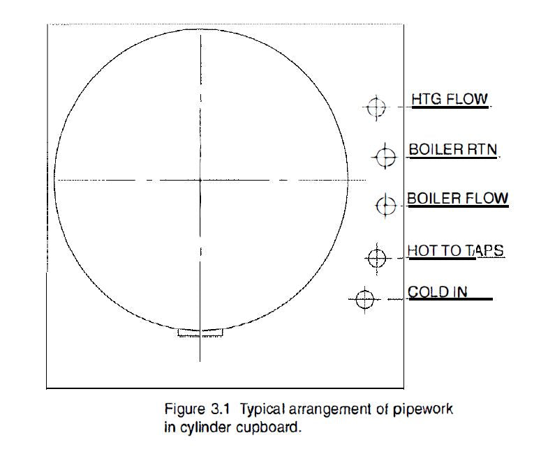
Plumbing Connections
1. Make all water connections in accordance with the labelling on the thermal store and the associated pipework as shown in Figure 3.1.
2. If a boiler is fitted above the thermal store, a gravity check valve should be incorporated in the connecting pipework leading from the BoilerMate Ill to the boiler i.e. the boiler return.
3. All factory made joints should be checked after installation in case they have been loosened during transit.
INSTALLATION
The electronic control system automatically regulates the domestic hot water outlet temperature to approximately 52°C and no adjustment or setting is necessary during installation.
This should always be set to maximum to give the best hot water and heating service and to achieve the highest efficiency and reduced boiler cycling by ensuring that the store thermostat will then be controlling the boiler.
When a range rated boiler is used it should always be set at the highest output. The system efficiency will not be impaired while the recovery rate will be improved.
1 . The boiler/system pump should be set at a speed at which the temperature difference across the boiler is not greater than 10°C. This adjustment should be made when the space heating is off.
2. The domestic hot water plate heat exchanger pump should always be set at maximum speed.
3. If it is necesary to replace either of the two pumps fitted to the appliance the pump head (motor pack) only should be removed as recommended by the manufacturer (Grunfoss). Assuming it is within warranty this will be accepted by a merchant as being under warranty as long as a complete pump i.e. alleged faulty motor pack and new base is left with the merchant. It is important when a pump has been replaced to ensure that any air is adequately vented
BoilerMate Ill installation is easier and quicker than a conventional vented system because there is no secondary feed and expansion cistern to install and no time is wasted in planning and installation of the controls and pumps in the cylinder cupboard.
1. Inspect the position in which BoilerMate Ill is to be fitted and check that the internal depth is at least 550mm and the width is 700mm for the model BM120, 600mm deep and 715mm wide for the model BM140 and 650mm deep and 770mm wide, for the BM180, BM200 and BM220 models. (See Figures 1.6 and 3.1 ).
2. Plan the pipe connections. Each fitting on the BoilerMate Ill has its own label. You need to connect the following pipes:
a) Pumped flow and return pipes from the body of the BoilerMate Ill to the radiators.
b) Pumped flow and return pipes from the body of the BoilerMate Ill to the boiler. c) Cold mains water supply connections to the inlet side of the plate heat exchanger and to the ball valve in the F & E cistern.
d) Domestic hot water supply pipe from the plate heat exchanger outlet to the taps.
e) Overflow/warning pipe from the F & E cistern to discharge in a conspicuous position externally.
3. If you are fitting the cistern remotely, check the route of the 22mm diameter open safety vent pipe and of the 15mm diameter feed and expansion pipe from the BoilerMate Ill to the cistern position. Also check the route of the overflow/warning pipe. All the BoilerMate Ill connections are clearly l abelled. When you have decided where the pipes are to be run, check the space for them inside the BoilerMate Ill compartment.
4. Decide at what stage in your installation work you are going to fit the BoilerMate 111. We would suggest that the BoilerMate Ill should be fitted first and the pipes run from it to the boiler, radiators and domestic hot water supply system subsequently in that order. If the BoilerMate Ill is installed early in the construction process ensure it is adequately protected or removed and refitted later. If it is decided to install the BoilerMate later in the construction process, the first fix pipework should enter the cylinder cupboard as shown in Figure 3.1
5. Remember that the automatic heating system bypass is already fitted and no additional bypass should be fitted in the system.
6. Carry out the rest of the installation work, i.e. boiler radiators and hot water supply pipework. Connect the cold water supply pipework.
7. Fill the BoilerMate Ill, radiators, boiler and pipework with water through the F & E cistern. Adjust the ballvalve so that when cold the water shuts off at, or just below, the level mark on the side of the cistern. Flush the system out, fill and vent again.
INSTALLATION
8. Open the domestic hot water isolating tap and establish flow through the taps etc. Check that the flow through all hot and cold water taps etc. is stopped when the mains water stop valve is closed.
9. The system now requires to be electrically connected.
10. The system is now ready to be commissioned.
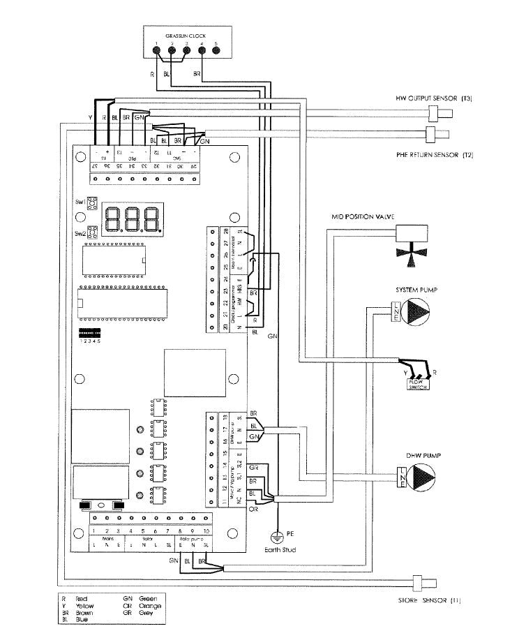
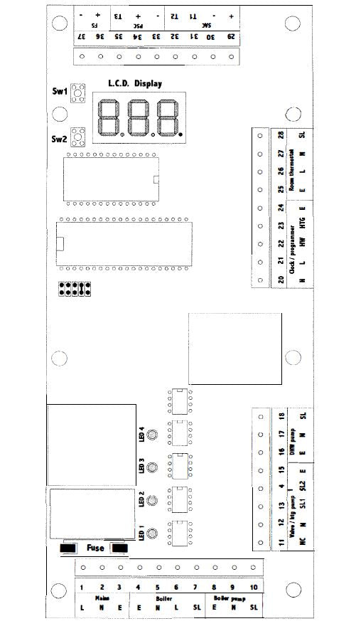
The BoilerMate Ill is pre-wired to a central control panel (see figure 3.2, page 18), and plumbers are well able to complete the electrical installation provided they adhere strictly to the IEE Regulations.
Note: Do not attempt the electrical work unless you are competent to carry it out to the above standards.
Fused Isolator
1. Connection to the electrical supply must allow complete electrical isolation by installing a double pole switch having a 3mm separation on both sides.
2. The isolating switch must only serve the BoilerMate Ill space heating and hot water system together with its controls and must be located within 1 metre of the appliance.
3. The supply to the BoilerMate Ill must be fused at 3A.
To Wire the BoilerMat
Before commencing, ensure that the power source to which the BoilerMate is to be connected is isolated. The generic wiring procedure for the BoilerMate is described below
1. Remove the white cover plate (4 screws) and run the external wiring through the grommets provided at the bottom of the white control panel.
2. From 3A fused and switched connection unit wire the mains power supply to the BoilerMate Ill storage appliance control PCB as follows:
• 'Live' to terminal '1'
• 'Neutral'to terminal '2'
'Earth' to terminal '3'
INSTALLATION
INSTALLATION
To wire a single channel space heating clock (no clock option)
• Connect neutral from PCB (term 20) to neutral terminal on the clock.
• Connect live from PCB (term 21) to live terminal on the clock.
• Connect earth from PCB (term24) to earth terminal on the clock.
• Connect switched live (heating) from the clock to terminal 23 on the PCB.
• Ensure that link L2 between terminals 21 and 22 is inserted.
Frost Protection
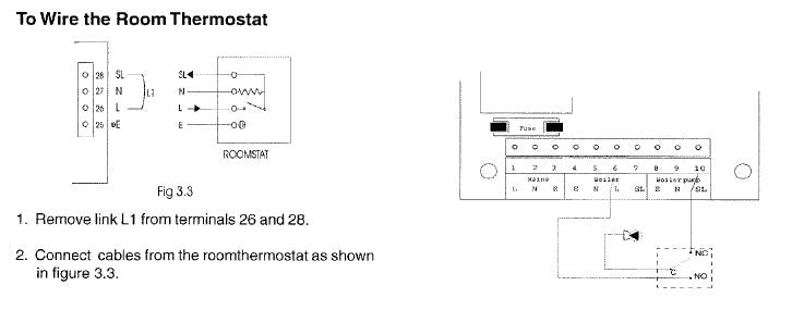
1. When frost protection is required for the whole house or where a base temperature is required during cold weather, then a frost thermostat should be wired across BoilerMate PCB terminals '21 'and '28'.
2. An alternative to fitting a frost thermostat would be to set the programmer to constant during the cold weather period, and adjust the room thermostat to a suitable setting.
3. When frost protection is required for the boiler circuit only a change over type pipe thermostat should be fitted on the primary return pipe adjacent to the boiler and wired into the boiler/system pump live as shown below.
COMMISSIONING
It is essential that the system functions properly for optimum performance. To achieve this, the primary system should be commissioned in accordance with good practice and generally in accordance with the requirements of BS6798, BS5449 and BS7593: 1992.
Cleansing the Primary System
1. Ensure that the float is correctly adjusted to close the ballvalve at the water level line inside the F & E cistern.
2. Fill the system and flush cold.
3. Refill the system.
4. Add a cleanser such as Sentinel X300 or Fernox Restorer/Superfloc to ensure that flux residues and installation debris are removed from the system. ( When determining the quantity of cleanser required, be sure to allow for the increased volume of water in the primary circuit due to the thermal store - see Table 1.1 for volumes).
5. In most cases the following quantities will be adequate for a typical 3/4 bedroom property When using either cleansing or corrosion inhibitor chemical, the manufacturers instructions must be followed.
6. Commission the boiler. a) If the boiler is range rated, then adjust it to the maximum heat input. b) Set the boiler/system pump speed so that the temperature difference across the boiler is less than 10'C. c) Set the boiler thermostat to maximum.
7. To ensure full cleansing, circulation to all parts of the system should continue for a minimum of 1 hour.
8. Flush the system hot having checked that there is no overflow when the system is up to temperature.
9. Refill the system.
10. Switch on and check the operation of the immersion heater (if fitted).
11 . Ensure that the 3 port motorized valve is in Auto position (i.e. not in manual locked position).
12. Ensure that the automatic bypass valve is set correctly to give approximately 1 O'C temperature rise across the boiler when the space heating is on.
Primary Water System Treatment
1. Although the standard BoilerMate Ill has no special water treatment requirements, the radiators and other parts of the circuit will benefit f rom the application of a scale and corrosion inhibitor such as Sentinel X100 or a Protector such as Fernox MB1.
2. When determining the quantity of inhibitor required, be sure to allow for the increased volume of water in the primary circuit due to the thermal store- see Table 1.1 for volumes.
3. In most cases the following quantities will be suitable for a typical 3/4 bed property.
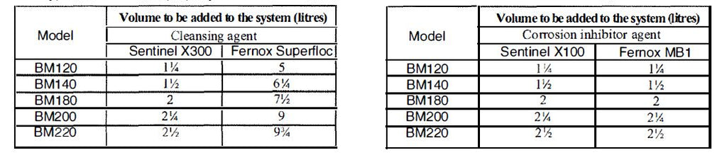
When using either cleansing or corrosion inhibitor chemical, the manufacturers instructions must be followed. Peel and paste 'boiler thermostat' label on suitable prominent location on the boiler.
Cleansing Hot/ Cold Water System Treatment
1. Fully flush and chlorinate the hot and cold water system in accordance with the recommendations in the Model Water Byelaws and BS6700.
2. Before finally filling the system check and clean the filter basket in the Y type strainer.
COMMISSIONING
For maximum system efficiency the store thermostat must be in control of the boiler i.e. the boiler cycles on the store thermostat and not on its integral thermostat. The BoilerMate control system will automatically commission itself to match the actual performance of the installed boiler. The control system must be checked and initialized as follows:
1. Set the boiler thermostat to MAXIMUM
2. Switch off heating on the programmer I room thermostat.
3. Switch off hotwater on the programmer if fitted.
4. Initialise the system as follows:-

COMMISSIONING
5. Check the operation of the controls as follows :·
(i) Switch on hot water on two channel clock if fitted. a. Horizontal LED bar 2 'store' will light on. LED display (if two channel clock not fitted then it will be permanently on). b. Boiler and pump will run and green LED's 1 and 2 will switch on.
(ii) Switch on space heating (programmer & room thermostat) a. Horizontal LED bar 1 'HT' will light. b. With pre version 19 program:- i) Green LED 3 on PCB will switch on. ii) 3-port valve will move to mid position. c. With version 19 onward program if the store temperature is greater than 60°C, then i) Green LED 3 on the PCB will switch on. ii) 3-port valve will move to mid position
(iii) Switch off space heating on programmer or room thermostat. a. Horizontal LED bar 1 'HT' will switch off. b. Green LED 3 on the PCB will switch off. c. 3 port valve will spring return to normal (i.e. hot water) position.
(iv) Open the hot water tap a. Horizontal LED bar 3 (bottom) on the LED display will light. b. Domestic hot water pump will run.
(v) Close the hot water tap a. Horizontal LED bar 3 will switch off. b. Domestic hot water pump will switch off.
6. Control functions have now been checked. Let the boiler heat the store and when the store is satisfied, i.e. commissioned green LED's 1 and 2 are off, the radiator circuit and hot water can be checked and balanced if required.
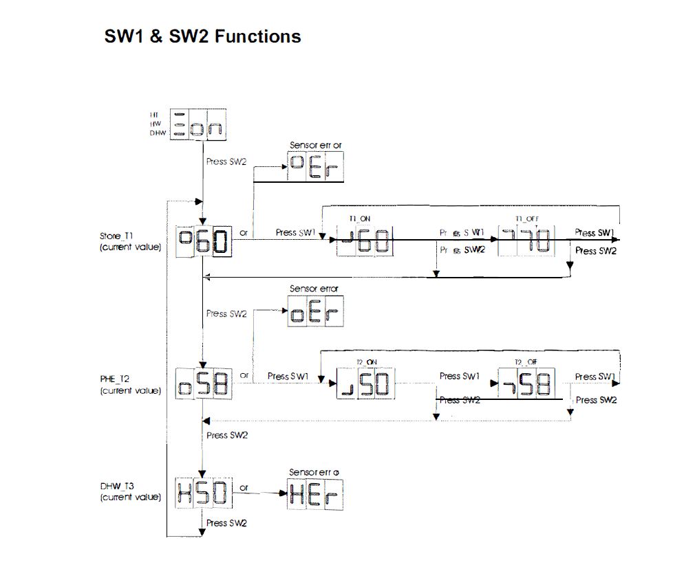
7. The temperature settings established during commissioning can be checked using push button switches sw1 and sw2 on the PCB as shown on page 25.
COMMISSIONING
1. DO check the incoming mains water pressure. The preferred range of mains pressure is 2 - 3bar.
2. DO check that all connections are in accordance with the labelling on the thermal store.
3. DO adjust the ballvalve so that the water level in the F & E cistern when the system is cold is at or just below the level mark inside the cistern.
4. DO make sure that there is adequate clearance above the F & E tank to service the ballvalve.
5. DO ensure that the range rated appliances are set at the highest output and the boiler thermostat is set to maximum for all boilers.
6. DO ensure that the water level in the expansion cistern is at least 250mm above the highest point on the radiator circuit or the highest point of the system.
7. DO insulate any exposed pipework in the BoilerMate cupboard.
8. DO plumb the overflow/warning pipe in a 20mm internal diameter pipe material which is suitable for use with a heating F & E cistern, in accordance with BS 5449 (such as copper) and ensure it discharges in a conspicuous external position.
9. DO check the pump settings. a) The boiler/system pump should be set to give a temperature difference across the boiler of 10°C or less. b) The hot water plate heat exchanger pump should be set at maximum.
10. DO ensure that the filter basket in the Y type strainer is removed cleaned and replaced prior to handover of the system.
11. DO ensure that the 3 port valve is in Auto position.
12. DO ensure that the bypass valve is set correctly.
13. DON'T use a combined feed and vent on BoilerMate installations.
14. DON'T use a BoilerMate on a sealed primary i.e. closed system.
15. DON'T use pipe smaller than 28mm between the boiler and the BoilerMate when the boiler rating exceeds 20kW (about 68,000 Btu/h).
16. DON'T use dipped flow and return between the boiler and the BoilerMate unless the boiler is fitted with an overheat thermostat. If necessary check with the suppliers.
FAULT FINDING/DIAGNOSTICS
Any fault in the system design and malfunction of system components will generate customer complaints. These complaints can be grouped into the following three main categories: -
a) The system is noisy
b) Hot water service is unsatisfactory
c) Space heating is unsatisfactory
CAUSES of a Noise System
1. Noisy pump operation
a) Check the level of water in the F & E cistern adjust and vent the pump/system if necessary.
b) Check the pump speed setting of the system/ boiler pump - reduce if necessary but ensure that the temperature rise across the boiler does not exceed 10°C.
c) If system is noisy when in heating mode -check and adjust if necessary the heating system bypass valve.
d) Check that the radiators are correctly balanced.
2. Noisy boiler operation
a) Check the flow rate through the boiler at full gas rate by measuring the temperature rise across the boiler. If the temperature rise is greater than 10°C, then increase the pump speed.
b) Check the level of water in the F & E cistern and the working head on the boiler.
c) Check and vent the system if necessary.
3. Noise when hot water tap is opened
a) If the plate heat exchanger pump is noisy when the hot water tap is opened, then check the level of water in the F & E cistern and vent the pump if necessary.
b) Water hammer - loose pipe work and/or tap washers.
CAUSES OF UNSATISFACTORY HOT WATER SERVICES
a. Check that the boiler flow temperature is adequate when it is switched off by either the internal or store thermostat -it should not be less than 80 °C.
c) If a separate hot water programmer or a two channel programmer is fitted, then check that the hot water 'on time' periods are set correctly to match the demand pattern in a dwelling.
d) Check that the store is charging to at least 75°C- if not then recommission.
e) Check that the hot water plate heat exchanger pump stops and starts when the hot water tap is opened and closed.
f) Check that the plate heat exchanger pump is set at maximum speed.
g) Check that the hot water outlet temperature does not change significantly when the hot water flow rate is increased from say 51/min to 151/min.
h) Check that the filter before the flow switch is not blocked - clean if necessary.
i) Check that the space heating and hot water load is not greater than the boiler output and that the BoilerMate Ill model is suitable for the type of dwelling. If 'a' to 'i' are correct then it is possible that the performance of the heat exchanger is impaired by scale. In this case the hot water flow rate will be noticeably less than the cold water flow rate. Replace it with a factory exchange unit and re-check hot water performance.
FAULT FINDING/DIAGNOSTICS
FAULT FINDING/DIAGNOSTICS
APPENDIX 5
WATER RELATED COSTS CAN BE REDUCED BY GOOD PLUMBING PRACTICE.
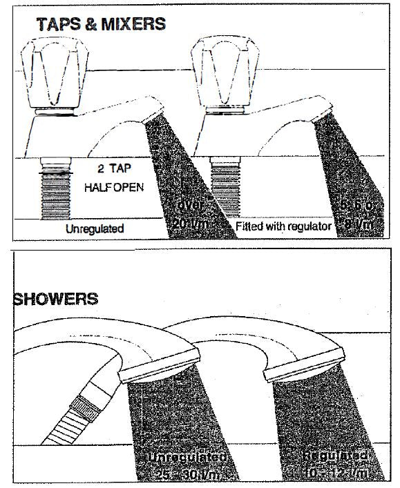
Vast quantities of water are needlessly run off to waste due to Taps, Mixers and Showers discharging flow rates far in excess of the rates required for them to perform their duties. The contrasting flow rates shown on this leaflet clearly illustrate the savings that can be made whilst still providing a good performance. British made AQUAFLOW REGULATORS provide constant flow rates by automatically compensating for supply pressure changes between 1 bar & 1 o bars. To facilitate installation into the wide range of plumbing equipment which is encountered in the U.K, FOUR FIXING OPTIONS are available:-
1. MXF "OW" RANGE - For fitting behind Fixed Shower Heads or onto Flexible Hoses for Handshowers (preferably onto the inlet end when lightweight hoses are used).
2. COMPRESSION FITIING RANGE. "In Line" regulators as in Option 4 for Taps & Mixers.
4 FIXING
1. MK RANGE - Combined Regulators & Aerator for screwing onto Taps & Mixers with internal or external threads on their noses. Anti Vandal models also available.
2. MR05-T RANGE - Internal Regulators. Push fit into Tap or Mixer seats. Produced in three sizes - 12.5mm (881010), 12mm & 10mm, Flangeless models also available for Taps with Low Lift washers.
3. MXF STANDARD RANGE- Screw on tail models for Taps & Mixers. Fix onto the tails before fitting the tap connectors. Available in 3/8", 1/2" ,3/4" and 1 11 BSP.
4. COMPRESSION FITIING RANGE -"In Line" regulators housed in 15mm & 22mm CXC COUPLERS & ISOLATING VALVES." "UK WFBS LISTED BY THE WATER RESEARCH CENTRE. Isolation valves available for slotted screwdriver operation or with coloured plastic handles. Now available also in plastic bodied push-fit couplers & valves.

Information by courtesy of
AQUAFLOW REGULATORS LTD
Haywood House, 40 New Road, Stourbridge, West Midlands DYS 1 PA
Telephone (01384) 442611 Fax: (01384) 442612
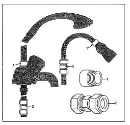
SHORT PARTS LIST
For Gledhill BoilerMate 3 Parts and Spares click on the following links: Gledhill BoilerMate 3 Parts And Spares
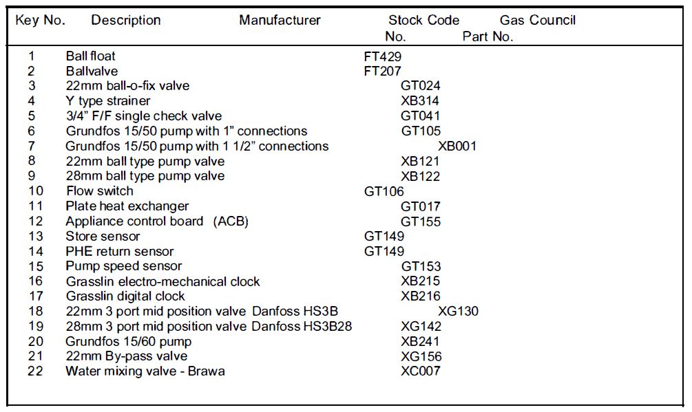
PARTS